
Color Display Apparatus

Inactive Publication Date: 2009-05-14
CANON KK
View PDF8 Cites 36 Cited by
  • Summary
  • Abstract
  • Description
  • Claims
  • Application Information

AI Technical Summary

Benefits of technology

[0025]An object of the present invention is to provide a color display apparatus capable of improving a light utilization efficiency.
[0031]In the color display apparatus according to the first aspect of the present invention, the hue change range of the medium is used when the three primary colors of red, green and blue, so that it is possible to not only improve the light utilization efficiency but also effect the multi-color display.

Problems solved by technology

On the other hand, as a disadvantage of the micro-color filter method, a transmittance is ⅓ of a monochromatic display method, so that a light utilization efficiency is low.
This low light utilization efficiency leads to a high power consumption of a back light or a front light in a transmission-type liquid crystal display apparatus having the back light or a reflection-type liquid crystal display apparatus having the front light.
However, it was impossible to display high-purity primary colors only by applying the YMC color filters to a monochromatic display device simply based on a conventional concept.
However, such display devices realizes bright display of monochromatic color but having failed to realize color display with a brightness comparable to that of paper as yet because they have no choice but to use a color filter similarly as in the liquid crystal display device.
However, this color display was based on a change in hue achieved by utilizing the birefringence effect, so that it was possible to control the hue by an amount of a voltage applied to the liquid crystal layer but it was difficult to obtain a high-purity display color.
In addition, it was also difficult to display smooth gradation color at the hue.

Method used


Image

  • Color Display Apparatus
  • Color Display Apparatus
  • Color Display Apparatus

Examples


first embodiment

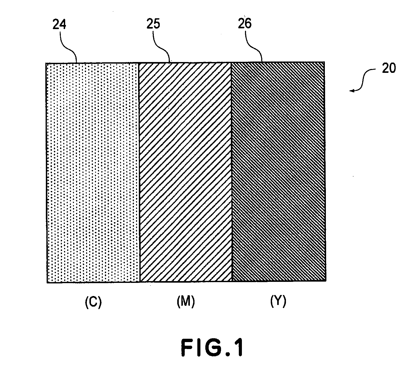
[0050]FIG. 1 shows a one pixel structure of a color display device used in a color display apparatus in this embodiment.

[0051]Hereinafter, a color display operation principle of the color display device will be described. The color display device used in the color display apparatus of the present invention may be those of various types. The display principle thereof will be described while taking a liquid crystal display device using a vertical (homeotropic) alignment (VA) mode on the basis of electrically controlled birefringence (ECB) effect, as an example.

[0052]As shown in FIG. 1, in the color (liquid crystal) display device in this embodiment, one pixel 20 is divided into a plurality of subpixels 24, 25 and 26 (three subpixels in this case) which are provided with color filters of yellow (Y), magenta (M), and cyan (C), respectively.

[0053]Here, at all the subpixels 24, 25 and 26, it is possible to utilize a change in luminance of achromatic color from black to white by appropriat...

second embodiment

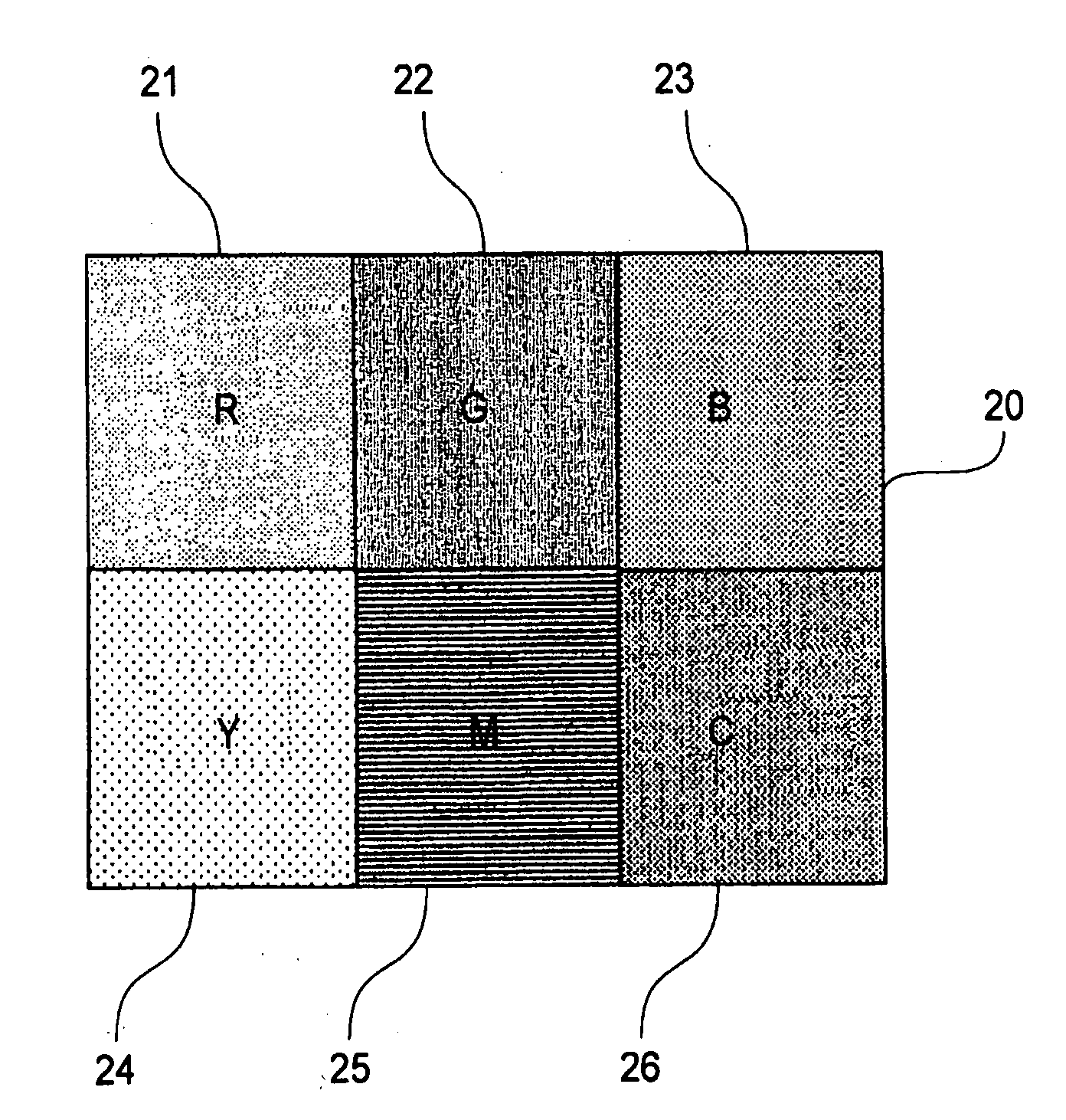
[0091]FIG. 8 shows a one pixel structure of a color display device used in a color display apparatus in this embodiment.

[0092]A display principle thereof will be described while taking a liquid crystal display device using liquid crystal having the ECB effect as an example, similarly as in First Embodiment.

[0093]As shown in FIG. 8, in the color (liquid crystal) display device in this embodiment, one pixel is divided into a plurality of subpixels 21 to 26 (six subpixels in this case) which are provided with color filters of red (R), green (G), blue (B), yellow (Y), magenta (M), and cyan (C), respectively.

[0094]Here, at all the subpixels 21 to 26, it is possible to utilize a change in luminance of achromatic color from black to white by appropriately adjusting a retardation of a liquid crystal layer. For example, at the time of displaying white, the colors of the color filters of RGB and YMC are displayed. In this case, when all the liquid crystal layers are placed in a white display ...

example 1

[0181]In this example, an active matrix substrate which has a diagonal size of 12 inches and 600×800 pixels and is provided with three types of color filters of yellow (Y), magenta (M) and cyan (C) through repetition of photolithographic process three times.

[0182]The thickness of the liquid crystal layer is adjusted to 5 μm, thus permitting a change in hue by retardation. However, an amount of retardation is insufficient, so that it is difficult to effect green display. In this case, the color filters are not used, so that display is effected at 3.1 V for yellow, 4.2 V for blue, and 5 V for cyan. In the liquid crystal display device, an image can be displayed by changing the applied voltage. It is possible to effect a continuous brightness modulation in a voltage range from 0 V to 2.8 V.

[0183]When the voltage of 2.8 V is applied at all the pixels, white display can be effected. A resultant reflectance is about 33%, thus being approximately two times that of the conventional liquid c...


PUM


Abstract

A color display apparatus is of the type wherein a unit pixel is constituted by at least three subpixels including first to third subpixels, and at each subpixel, a medium for changing an optical property depending on a voltage applied thereto is disposed. The color display apparatus includes means for applying a voltage, to each of the first to third subpixels, for changing the optical property of the medium within a brightness change range in which light passing through the medium is changed in brightness and a hue change range in which the light passing through the medium assumes chromatic color and a hue of the chromatic color is changed while including combinations of red and green, red and blue, and green and blue for the first to third subpixels, respectively.

Description

TECHNICAL FIELD[0001]The present invention relates to a color display apparatus.BACKGROUND ART[0002]At present, a flat-panel display as an embodiment of a color display apparatus has widely been popularized as various monitors for a personal computer and the like and as a display apparatus for a cellular phone, and so on. In the future, the flat-panel display is expected to follow popularization more and more, such as development in use for big-screen television.[0003]A most popular flat-panel display is a liquid crystal display apparatus. As a color display method for the liquid crystal display apparatus, one called a micro-color filter method has been used widely.[0004]The micro-color filter method effects full-color display by constituting one unit pixel with at least three pixels and providing the three pixels with color filters of three primary colors of red (R), green (G), and blue (B), respectively, thus having an advantage of readily realizing a high color-reproducing perfor...

Claims


Application Information

Patent Timeline
IPC IPC(8): G09G3/36G02F1/1335G02F1/1343G02F1/139
CPCG02F1/133514G02F2203/34G02F2001/134345G02F1/1393G02F1/134345
Inventor ASAO, YASUFUMINAGAYAMA, KOHEIISOBE, RYUICHIROMORI, HIDEOTANAKA, HIRONAOMATSUDA, HIROSHI
Owner CANON KK
Learn More