Polarizing plate with an optical compensation layer and image display apparatus using the same
a technology of optical compensation layer and polarizing plate, which is applied in the direction of optics, polarising elements, instruments, etc., can solve the problems of degrading optical properties, not being overcome, and degradation of contrast, and achieve the reduction of the thickness of the image display apparatus, and the suppression of the thermal expansion difference between the polarizer and the optical compensation layer during the use under a high-temperature environmen
- Summary
- Abstract
- Description
- Claims
- Application Information
AI Technical Summary
Benefits of technology
Problems solved by technology
Method used
Image
Examples
example 2
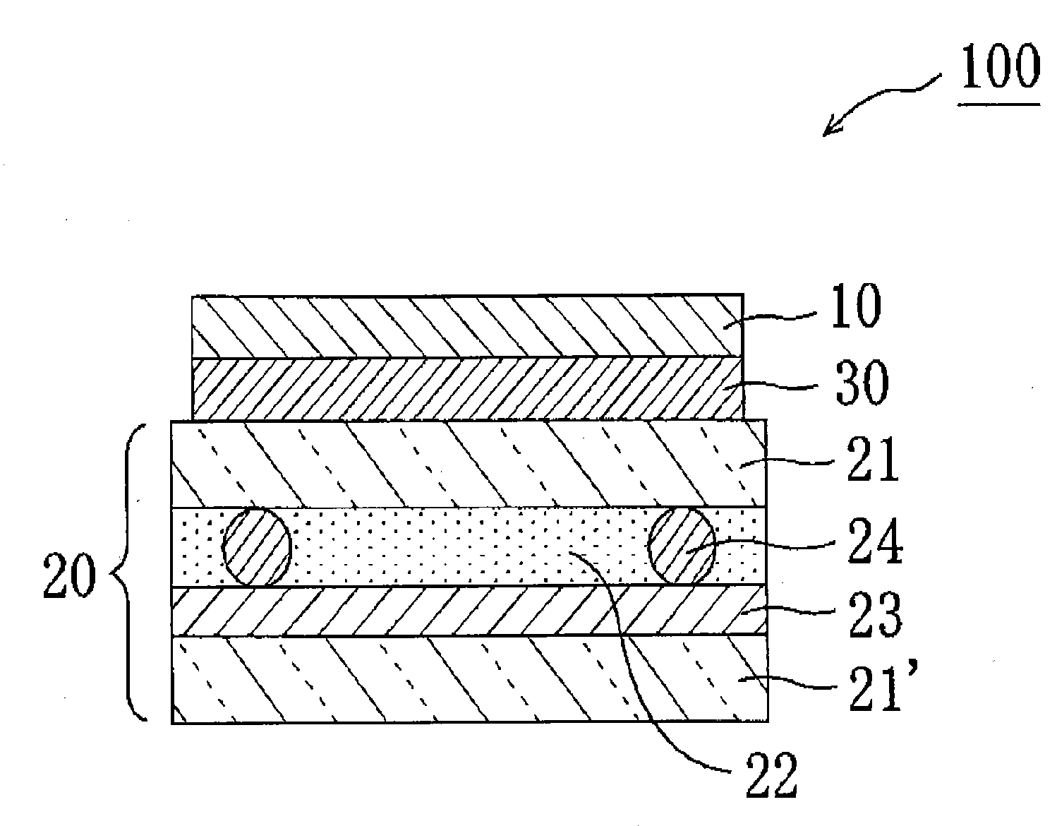
[0200]A polarizing plate, a first optical compensation layer, and a second optical compensation layer were produced in the same way as in Example 1.
[0201](Production of a Third Optical Compensation Layer)
[0202]A long norbornene-based resin film (Arton (trade name) manufactured by JSR, thickness: 100 μm, photoelastic coefficient: 5.00×10⁻¹² m2 / N) was longitudinally stretched about 1.27 times at 175° C. and laterally stretched about 1.37 times at 176° C., whereby a long film for a third optical compensation layer (thickness: 65 μm) was produced. The film was punched to a size of 20 cm (longitudinal direction)×30 cm (lateral direction) to obtain a third optical compensation layer. An in-plane retardation Re3 of the third optical compensation layer was 0 nm, and a thickness direction retardation Rth3 thereof was 110 nm.
[0203](Production of a Polarizing Plate with an Optical Compensation Layer)
[0204]A polarizing plate with an optical compensation layer was produced in the same way as in ...
example 3
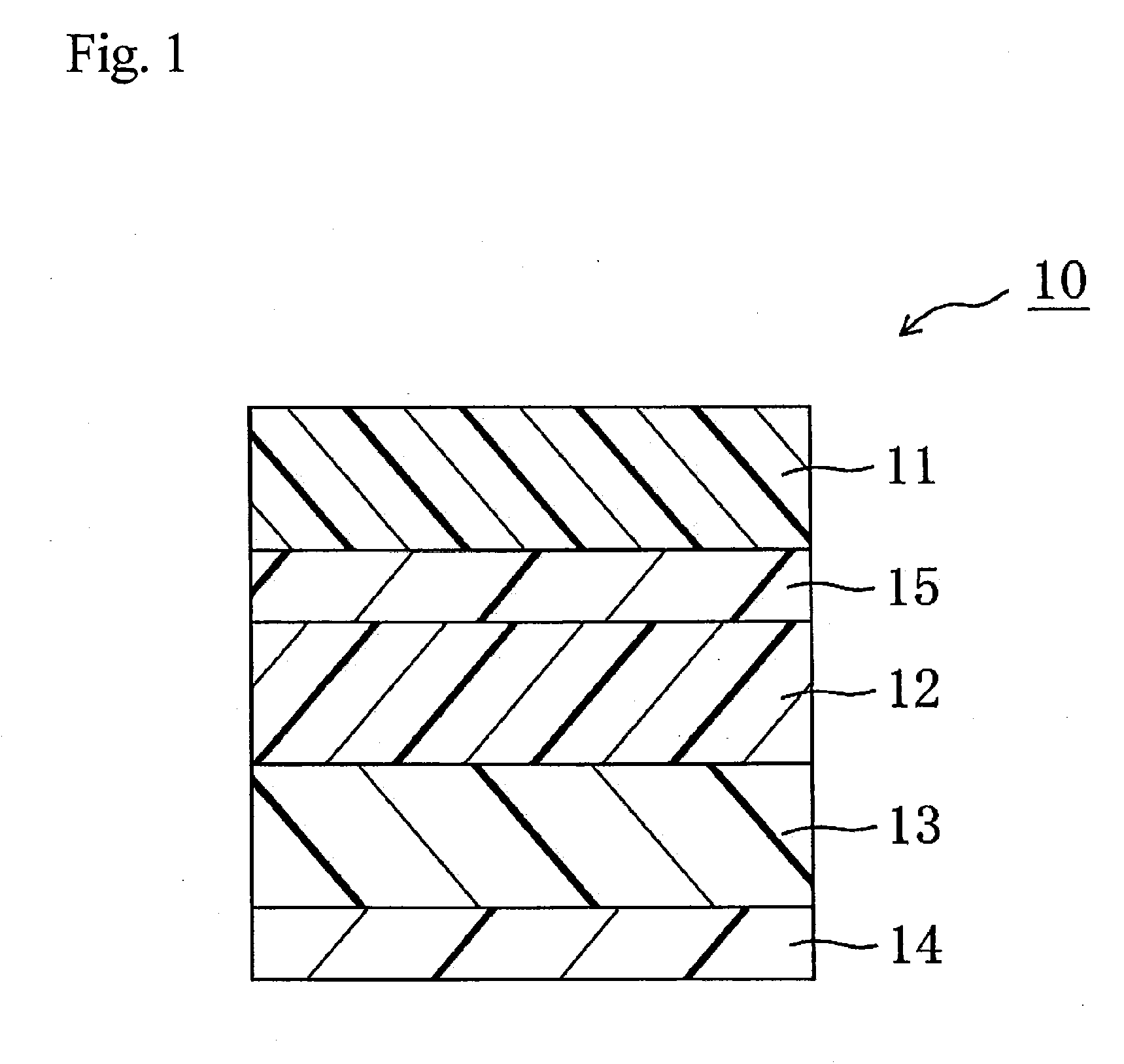
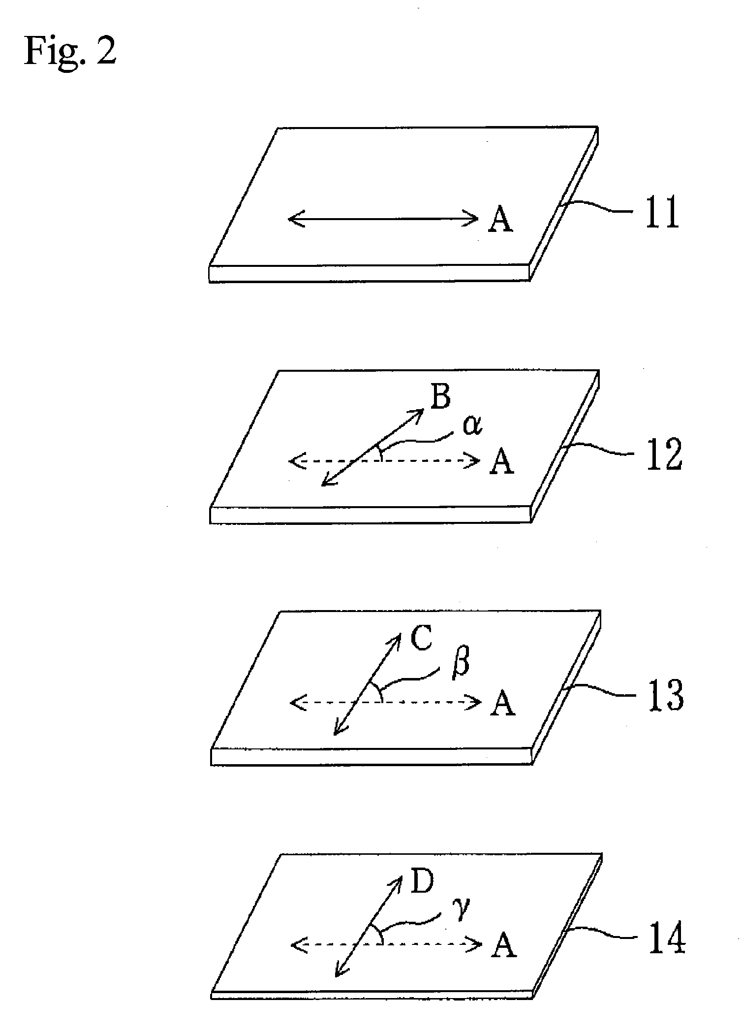
[0205]A polarizing plate with an optical compensation layer was produced in the same way as in Example 1, except that the slow axis of the first optical compensation layer was set to form an angle of 35° in a counterclockwise direction with respect to the absorption axis of the polarizer of the polarizing plate. The thickness, transmittance, and heat unevenness of the obtained polarizing plate with an optical compensation layer were measured. The results are shown in Table 1 above.
example 4
[0206]A polarizing plate with an optical compensation layer was produced in the same way as in Example 1 except that the slow axis of the second optical compensation layer was set to form an angle of 35° in a counterclockwise direction with respect to the absorption axis of the polarizer of the polarizing plate. The thickness, transmittance, and heat unevenness of the obtained polarizing plate with an optical compensation layer were measured. The results are shown in Table 1 above.
PUM
 Abstract
Description
Claims
Application Information
 - R&D
- Intellectual Property
- Life Sciences
- Materials
- Tech Scout
- Unparalleled Data Quality
- Higher Quality Content
- 60% Fewer Hallucinations
Browse by: Latest US Patents, China's latest patents, Technical Efficacy Thesaurus, Application Domain, Technology Topic, Popular Technical Reports.
© 2025 PatSnap. All rights reserved.Legal|Privacy policy|Modern Slavery Act Transparency Statement|Sitemap|About US| Contact US: help@patsnap.com


