
Projector

a projector and projector body technology, applied in the field of projectors, can solve the problems of reducing the size increasing the size and cost of the system, and limiting the size reduction of the entire device, so as to achieve the effect of reducing the size and cost, and widening the lens

Inactive Publication Date: 2009-05-14
SEIKO EPSON CORP
View PDF3 Cites 9 Cited by
  • Summary
  • Abstract
  • Description
  • Claims
  • Application Information

AI Technical Summary

Benefits of technology

[0008]It is an advantage of some aspects of the invention to provide a projector capable of easily achieving size and cost reduction and meeting the demand for wider lens.
[0010]According to this projector, the entire or partial area of the refraction unit and the image forming unit are disposed on the non-projection side of the screen or on the extension plane of the screen. In this case, the projection light released from the image forming unit is bended by the bending mirror in the vicinity of the screen and guided toward the area before the screen. The bended projection light reaches the reflection unit on the projection side of the screen to provide close projection on the screen. When the refraction unit and the reflection unit are disposed with the screen interposed therebetween, for example, the positioning of the reflection unit, the refraction unit and the image forming unit can be balanced by disposed on the non-projection side and the projection side of the screen and contribute to space-saving. Thus, the entire thickness of the projector can be reduced. Moreover, the reflection unit is a curved surface mirror. In this case, the size of the curved surface mirror can be reduced, and extrusion of the projector toward the projection side of the screen can be decreased. Accordingly, the projection size of the projector on the screen can be increased with reduced size and cost of the projector.
[0011]It is preferable that the curved surface mirror has either a concave surface or a convex surface as a curved reflection surface. When the curved surface mirror has a concave surface, extrusion of the curved surface mirror to below is smaller than that of the curved surface mirror as the convex surface. In this case, the projection image can be enlarged with reduced projection space before the screen. When the curved surface mirror is a convex surface, the projection size is larger than that of the concave surface. Moreover, the radius of curvature of the convex surface mirror can be made smaller than that of the concave surface mirror. Thus, manufacture of the convex surface mirror is easier. The curved reflection surface herein refers to a reflection optical surface which reflects real projection light by a curved surface mirror.
[0013]It is preferable that the refraction unit has a plurality of lenses. According to this structure, the angle of view can be increased with high accuracy, and the variable power function can be added.
[0014]It is preferable that the bending mirror is disposed between the plural lenses. According to this structure, the distance between the curved surface mirror and the exit side end of the refraction unit can be shortened, and thus the curved surface mirror can be made relatively compact.
[0015]It is preferable that the all or partial optical axis of the plural lenses is disposed parallel with the extension plane of the screen on either the non-projection side of the screen or the extension plane of the screen. According to this structure, the plural lenses are disposed in parallel on either the non-projection side or the extension plane of the screen, and thus the space for disposing the refraction unit can be reduced.

Problems solved by technology

Thus, the entire size and cost of the system increase.
Thus, size reduction of the entire device is limited.

Method used


Image

  • Projector
  • Projector
  • Projector

Examples


first embodiment

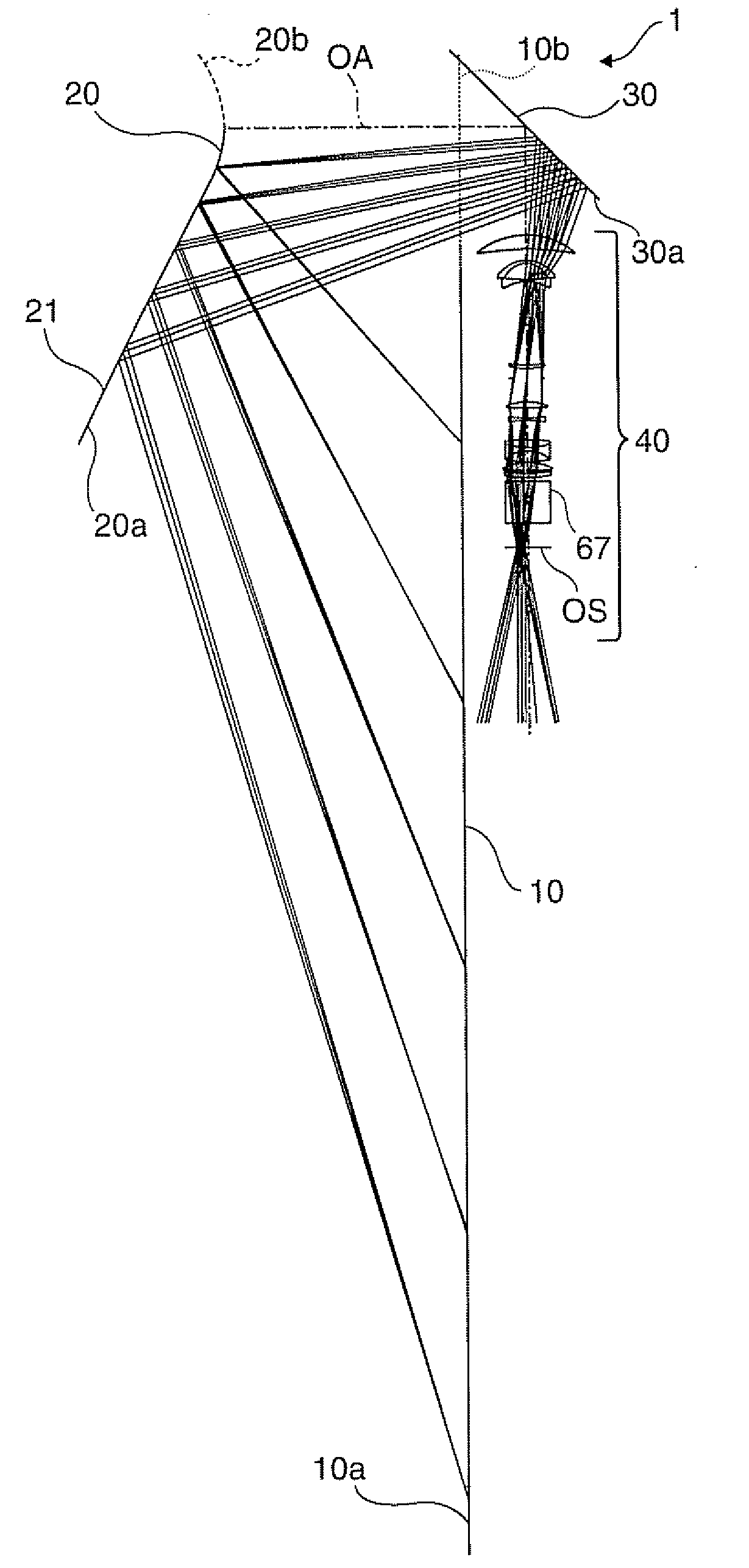
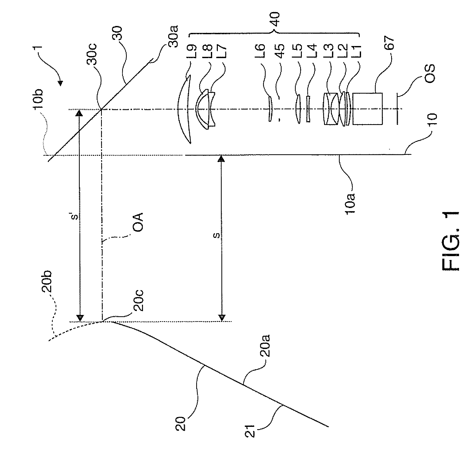
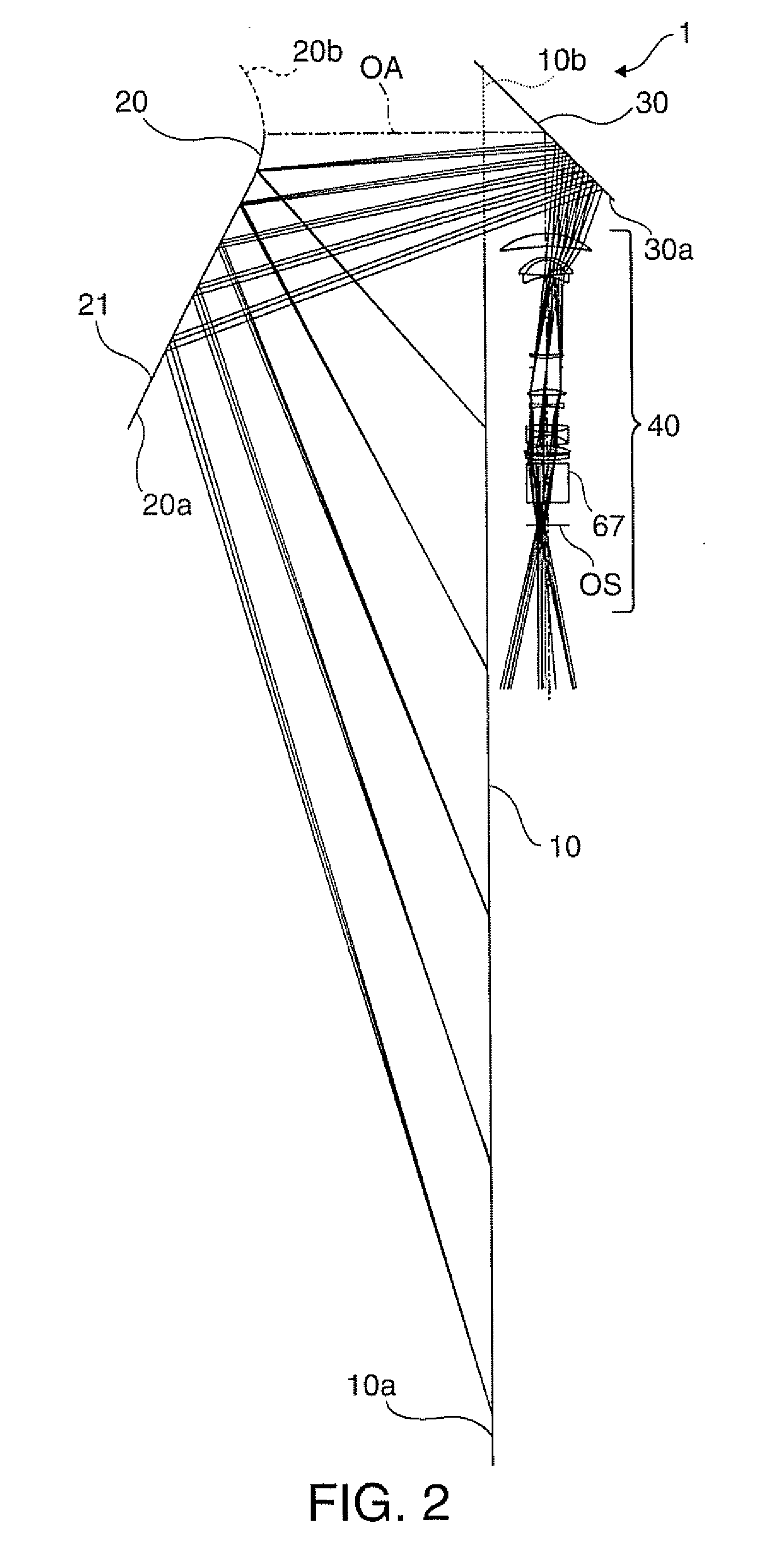
[0032]FIGS. 1 through 3 are side views illustrating a main part of a projector according to a first embodiment of the invention. FIG. 1 illustrates a concept of the main part structure of the projector. FIG. 2 illustrates light condition within the projector. FIG. 3 is an enlarged view of FIG. 2.

[0033]A projector 100 in this embodiment includes a screen 10, a reflection unit 20, a bending mirror 30, a refraction unit 40, and an image forming unit 60. In this structure, the reflection unit 20 and the refraction unit 40 constitutes a projection system 1. In FIGS. 1 through 3, only a cross dichroic prism 67 is shown in the image forming unit 60 as a part thereof, and other parts of the image forming unit 60 are not shown.

[0034]The screen 10 is a reflection type projection plate, and displays an image by diffuse reflect of projection light via a screen projection surface 10a. The screen 10 is made of white plastic plate, for example. The screen 10 may be manufactured by applying coating...

second embodiment

[0055]FIGS. 6 through 8 are side views illustrating a main part of a projector according to a second embodiment of the invention. FIG. 6 illustrates a concept of the main part structure of the projector. FIG. 7 illustrates light condition within the projector. FIG. 8 is an enlarged view of FIG. 7. A projector 200 in this embodiment is a modification of the projector 100 in the first embodiment shown in FIG. 1 or other figures, and parts included in the projector 200 similar to those in the projector 100 in the first embodiment are not specifically explained.

[0056]The projector 200 in this embodiment includes the screen 10, a reflection unit 120, the bending mirror 30, a refraction unit 140, and the image forming unit 60. In this structure, the reflection unit 120 and the refraction unit 140 constitute a projection system 2. In FIGS. 6 through 8, only the cross dichroic prism 67 as a part of the image forming unit 60 is shown, but other parts are not shown.

[0057]The reflection unit 1...

third embodiment

[0065]FIGS. 9 through 11 are side views illustrating a main part of a projector according to a third embodiment of the invention. FIG. 9 shows a concept of the main part structure of the projector. FIG. 10 illustrates light condition within the projector. FIG. 11 is an enlarged view of FIG. 10. A projector 300 in this embodiment is a modification of the projectores 100 and 200 according to the first and second embodiment shown in FIGS. 1 and 6, and other figures, and parts included in the projector 300 similar to those in the projectores 100 and 200 in the first and second embodiments are not specifically explained.

[0066]The projector 300 in this embodiment includes the screen 10, a reflection unit 220, the bending mirror 30, a refraction unit 240, and the image forming unit 60. In this structure, the reflection unit 220 and the refraction unit 240 constitute a projection system 3. In FIGS. 9 through 11, only the cross dichroic prism 67 as a part of the image forming unit 60 is show...


PUM


Abstract

A projector includes a screen; a reflection unit having at least one curved surface mirror disposed on the projection side of the screen; a bending mirror disposed before the reflection unit on the optical path and disposed on either the non-projection side of the screen or on an extension plane of the screen; a refraction unit disposed before the reflection unit on the optical path and having at least a part disposed on either the non-projection side of the screen or on the extension plane of the screen; and an image forming unit disposed before the refraction unit on the optical path and disposed on the non-projection side of the screen.

Description

BACKGROUND[0001]1. Technical Field[0002]The present invention relates to a projector for projecting an image formed by a liquid crystal panel or the like on a screen.[0003]2. Related Art[0004]As a technology for projecting an image on a screen by using a projector disposed in the vicinity of the screen, a method which locates a projector below the screen and reflects an image by an upper mirror to project the image on the screen (for example, see JP-A-2-196230), a method which locates a projector behind the screen and repeats projection by using two flat plates (for example, see JP-A-10-206969), and other methods have been proposed. Also, there are other method which directly attaches the projector on an arm extending from the screen (for example, see JP-T-2002-538508), and method which provides enlarged close projection on the screen by using a projection system which includes refraction system containing plural lenses and a reflection mirror (for example, see JP-A-2004-258620 and ...

Claims


Application Information

Patent Timeline
IPC IPC(8): G03B21/28
CPCG02B17/0852G03B21/28G02B17/0856
Inventor MINEFUJI, NOBUTAKA
Owner SEIKO EPSON CORP
Learn More