Micro fluid device and trace liquid diluting method

a microfluidic device and liquid diluting technology, applied in the field of microfluidic devices, can solve the problems of large mixture ratios, microfluidic devices that fail to work, and sections from measuring sections cannot coincide, so as to shorten the operation period, shorten the magnification period, and facilitate the transportation of micro-droplets in each combination.

Active Publication Date: 2009-05-21
SEKISUI CHEM CO LTD
View PDF14 Cites 33 Cited by
  • Summary
  • Abstract
  • Description
  • Claims
  • Application Information

AI Technical Summary

Benefits of technology

[0030]The microfluidic device concerning the present invention has a micro-channel structure formed in the substrate. The micro-channel structure has a first mixing unit, and a second mixing unit connected to the downstream of the first mixing unit. Since a first and a second micro-droplets supplied from a first and a second measuring section are merged in a merging section, and then they are mixed in a mixing section in each mixing unit, the mixed droplet obtained by mixing the first and the second micro-droplets having been exhausted from the first and the second measuring sections may be removed out in each of the mixing unit. Furthermore, since either of outlet ports of the first to the third outlet ports of the first mixing unit is connected to one or both of the first or the third inlet port of the second mixing unit, the mixed droplet may be obtained from the first and the second mixing units, respectively, or the mixed droplet having each different concentration may be obtained as the mixed droplet by diluting the second or the first micro-droplet with the first or the second micro-droplet, in each mixing unit.
[0031]Accordingly, a plurality of diluted micro-droplets, and diluted micro-droplets having a plurality of kinds of concentrations may easily and promptly be prepared in a microfluidic device configured using a single substrate.
[0032]Especially, since the micro-droplet mixed by the first mixing unit is used as a fixed amount of the first, or the second micro-droplet in the second mixing unit, when the second outlet port of the first mixing unit, is connected to the first or the third inlet port of the second mixing unit, a micro-droplet diluted at a higher magnification may be obtained in the second mixing unit.
[0033]Conventionally, micro-channel structures with a plurality of stages having a plurality of mixing units connected with each other have not been adopted in this kind of microfluidic devices. The reason is as follows. In this kind of microfluidic devices, an extremel...

Problems solved by technology

However, the microfluidic device provided with the trace amount of liquid measuring structure described in the patent document 2 has a problem that larger mixture ratios set as not less than 10 times fail to provide mixing exhibiting accuracy and excellent reproducibility.
However, conventionally, the kind of microfluidic devices failed to work as micro-channel structures having a plurality of mixing units in a plurality of stages connected with each other.
However, in a connected system of a plurality of mixing units, since there is restriction that the s...

Method used


Image

  • Micro fluid device and trace liquid diluting method
  • Micro fluid device and trace liquid diluting method
  • Micro fluid device and trace liquid diluting method

Examples


Embodiment Construction

[0105]Hereinafter, the present invention will be described with reference to detailed embodiments and drawings of the present invention.

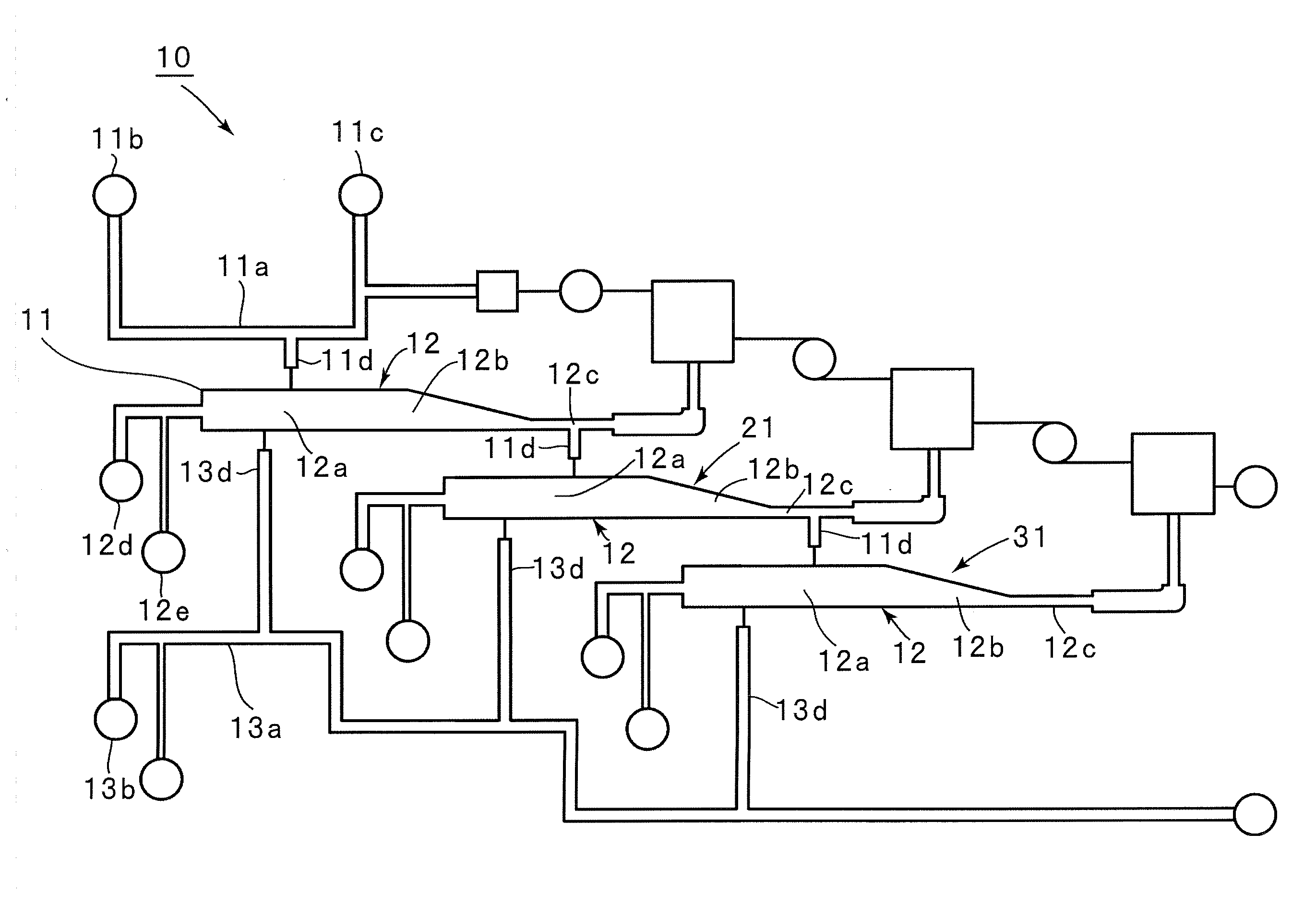
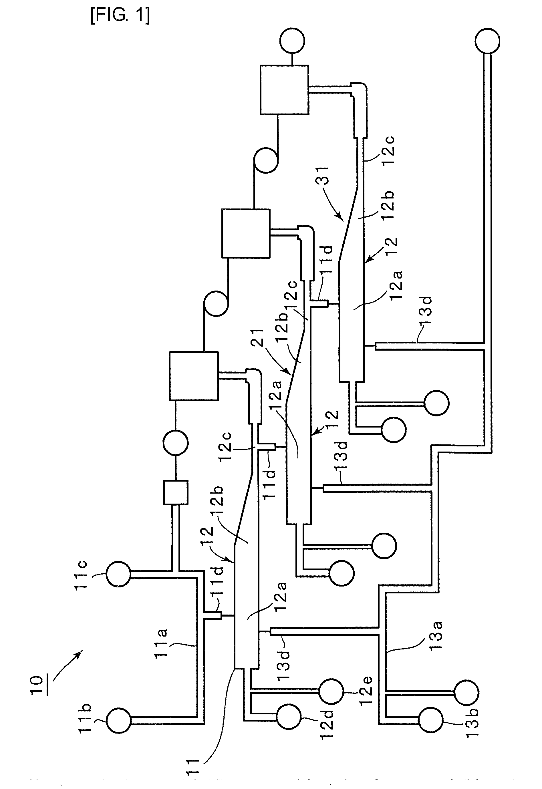
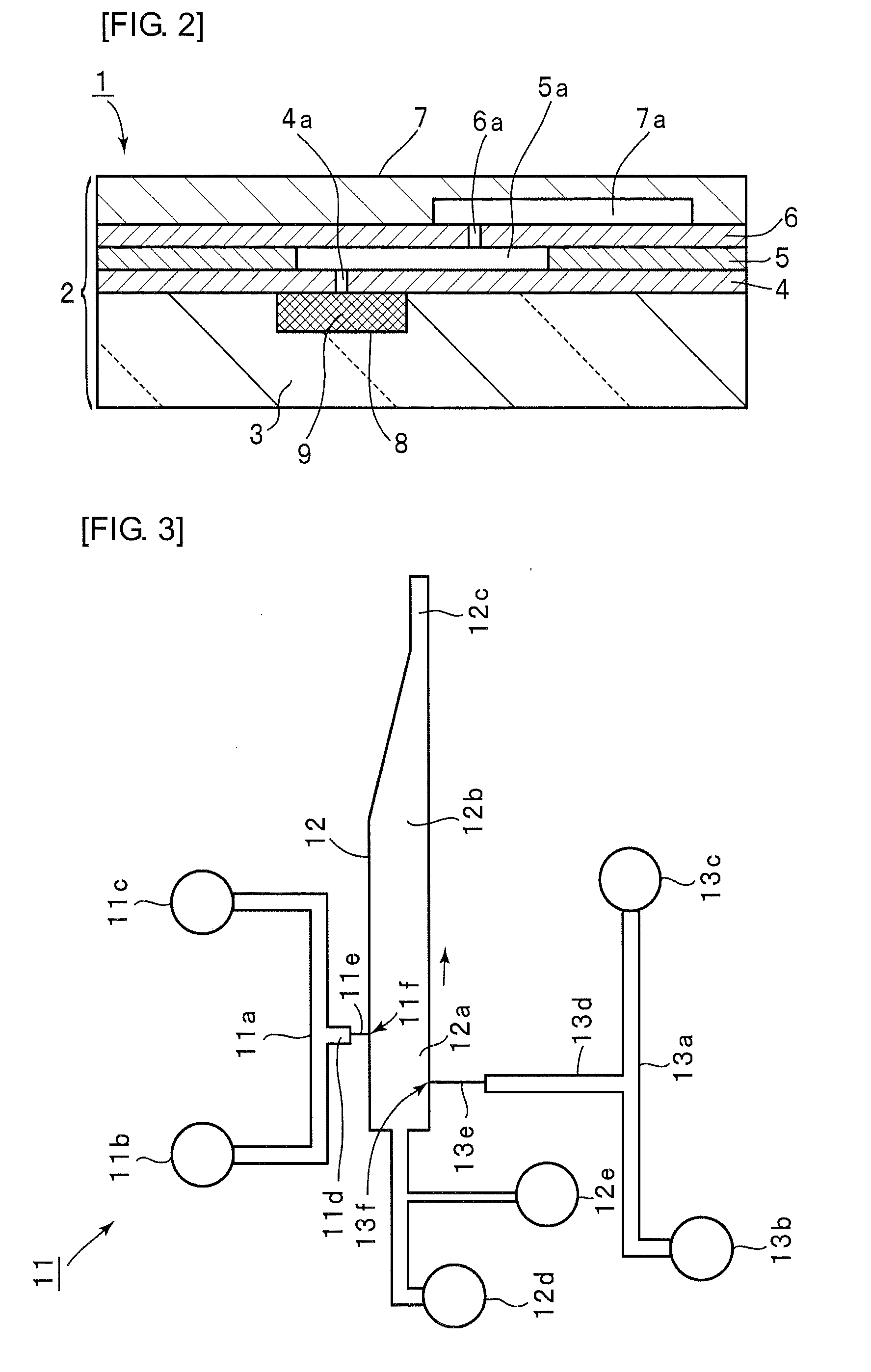
[0106]FIG. 1 is a schematic plan view illustrating a micro-channel structure of a microfluidic device concerning an embodiment of the present invention, and FIG. 2 is a front sectional view illustrating schematically a part of a microfluidic device of the embodiment.

[0107]As illustrated in FIG. 2, a microfluidic device 1 has a substrate 2. The substrate 2 has a structure having a transparent base plate 3, intermediate plates 4 to 6, and a top plate 7 laminated therein. A gas generating chamber 8 is provided in the base plate 3. The gas generating chamber 8 has an opening on the upper surface of the base plate 3, and a gas generating component 9 for generating a gas responsive to irradiation of a light or heating is stored in the gas generating chamber 8. Storing of the responsive gas generating component 9 in the above-described gas generating chamb...


PUM

PropertyMeasurementUnit
Concentrationaaaaaaaaaa
Widthaaaaaaaaaa
Heightaaaaaaaaaa

Abstract

A microfluidic device provided with a micro-channel structure capable of easily and positively providing therein micro-droplet having various dilution ratios. A micro-channel structure provided in a substrate (2) has a first mixing unit (11) and a second mixing unit (21) connected to the downstream side of the first mixing unit (11), with each mixing unit (11, 21) having first through third micro-channels. One end of a first weighing unit (11d) consisting of a micro-channel having a capacity equivalent to the volume of a specified-amount first micro-droplet is opened to a first micro-channel (11a), and the other end is opened to a merging unit (12a) provided on a second micro-channel (12). One end of a second weighing unit (13d) consisting of a micro-channel having a capacity equivalent to the volume of a specified-amount second micro-droplet is connected to a third micro-channel (13), and the other end is opened to the merging unit (12a). Any one of the first through third outlet ports of the first mixing unit is connected with the first or the third inlet port of the second mixing unit (21).

Description

TECHNICAL FIELD[0001]The present invention relates to a microfluidic device having a micro-channel structure, formed in a substrate, for mixing a micro-droplet, and in more detail, the present invention relates to a microfluidic device used for mixing or diluting samples, reagents, etc. for various analyses.BACKGROUND ART[0002]Conventionally, samples and reagents are often diluted in analysis for samples and in chemical reaction of various substances. Especially, in the case of dilution of trace amount of liquid, an operation method using a microplate and distributive pouring pipette or a method of using a dispensable robot device has been used. On one hand, the operation method using a microplate and a distributive pouring pipette have needed a complicated operation and an experienced experimenter. Furthermore, simple mixing operation of samples and reagents has been difficult outside of the laboratory or in a bedside for clinical laboratory test, etc.[0003]On the other hand, dilut...

Claims


Application Information

Patent Timeline
IPC IPC(8): G01N35/10
CPCB01F13/0071B01F15/0404B01F2013/1052B01F2015/0221B01J2219/00889G01N2035/00465B01L2200/0605B01L2300/0816B01L2300/0867B01L2400/0487B01L3/502792Y10T137/87652Y10T137/87249B01F33/3021B01F33/834B01F35/715B01F35/81B01J19/00G01N35/08B01F23/40B01F25/00
Inventor YAMAMOTO, KAZUKIFUKUI, HIROJISEKI, MINORU
Owner SEKISUI CHEM CO LTD
Why Eureka
Try Eureka