Method and system for locating sensor node in sensor network using transmit power control

a sensor network and transmit power control technology, applied in the field of sensor networks, can solve the problems of large error between the determined position and the actual position, and achieve the effect of reducing the amount of traffic generated in the network, reducing the error range, and advantageously more cost-effectiv

Active Publication Date: 2009-05-21
SAMSUNG ELECTRONICS CO LTD +1
View PDF10 Cites 7 Cited by
  • Summary
  • Abstract
  • Description
  • Claims
  • Application Information

AI Technical Summary

Benefits of technology

[0018]In another exemplary aspect of the present invention, the location of a sensor node may be identified using transmission range control and position mapping. Reference nodes send location information upon request from sensor nodes, thereby reducing the amount of traffic generated in the network. Compared with triangulation, an exemplary aspect of the method of the present invention may perform more operations, but result in a smaller error range by using location information collected from, for example, four reference nodes forming a square to calculate its own location. In addition, the RF module of the present invention is advantageously more cost-effective than a module using a different wireless medium, and can be widely utilized.

Problems solved by technology

RF-based position location may result in a large error in the determined position and the actual position, because RF signals are very sensitive to external environmental conditions.

Method used


Image

  • Method and system for locating sensor node in sensor network using transmit power control
  • Method and system for locating sensor node in sensor network using transmit power control
  • Method and system for locating sensor node in sensor network using transmit power control

Examples


Embodiment Construction

[0031]Hereinafter, exemplary embodiments of the present invention are described in detail with reference to the accompanying drawings. The examples shown and described herein are provided for illustrative purposes only, and the claimed invention is not limited to the examples shown and described. The same reference symbols are used throughout the drawings to refer to the same or similar parts. For the purposes of clarity and simplicity, detailed descriptions of well-known functions and structures incorporated herein may be omitted to avoid obscuring appreciation of the subject matter of the present invention by a person of ordinary skill in the art.

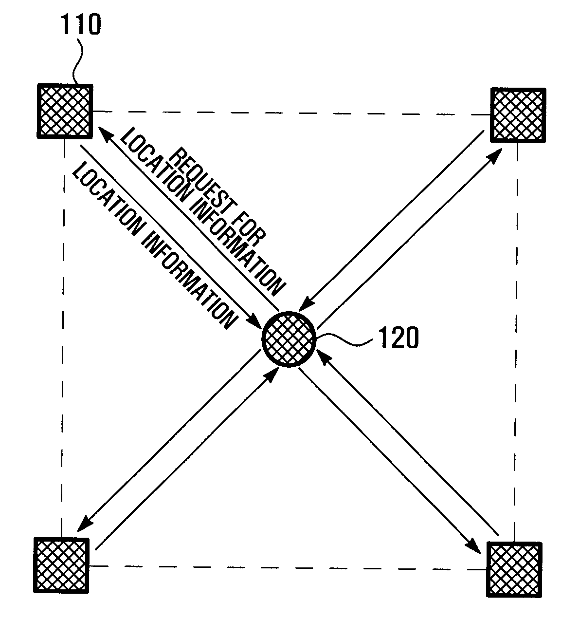
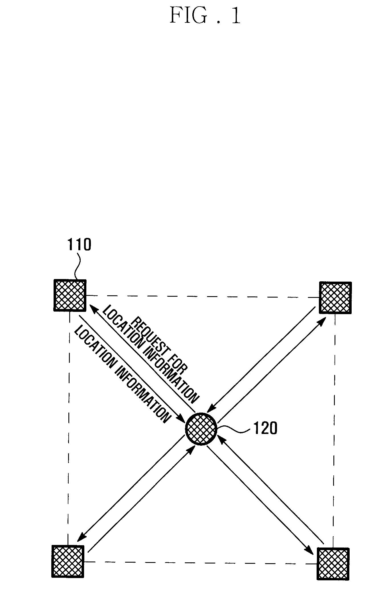
[0032]In the description hereinbelow, a reference node is typically a node that is aware of its own absolute position. Upon reception of a signal requesting location information from a sensor node, the reference node sends location information to the sensor node while varying transmission power. The position of a reference node may be cha...


PUM


Abstract

A method and apparatus for a sensor network having a plurality of reference nodes and a sensor node that enables the sensor node to compute a relative position through transmission range control and position mapping. In transmission range control, each reference node sends location information signals to the sensor node while varying transmission power. In position mapping, the sensor node forms a grid of vertical and horizontal lines corresponding to a square area defined by the neighboring reference nodes, extracts coordinates of intersections in the grid belonging to a shared region between areas covered by location information signals of various transmit power levels from the neighboring reference nodes, and sets the position of the sensor node to the middle points of the extracted coordinates. Each reference node sends a location information signal when a random backoff time expires after reception of a location information request signal.

Description

CLAIM OF PRIORITY[0001]This application claims priority to an application entitled “METHOD AND SYSTEM FOR LOCATING SENSOR NODE IN SENSOR NETWORK USING TRANSMIT POWER CONTROL” filed in the Korean Intellectual Property Office on Nov. 15, 2007 and assigned Serial No. 2007-0116815, the contents of which are incorporated herein by reference in its entirety.BACKGROUND OF THE INVENTION[0002]1. Field of the Invention[0003]The present invention relates generally to a sensor network including reference nodes and sensor nodes. More particularly, the present invention relates to a sensor node locating method and system that enable a sensor node to receive location information signals with successively varying signal strength from plural reference nodes and to compute the coordinates of the location of the sensor node and an associated error.[0004]2. Description of the Related Art[0005]It is expected that various new services will be created in the near future through ubiquitous computing or ubi...

Claims


Application Information

Patent Timeline
Patent Type & Authority Applications(United States)
IPC IPC(8): H04Q5/22
CPCG08C21/00G01S5/021G01S5/0236G01S5/0252G01S5/0289G01S5/14
Inventor RYU, JEHYOKKIM, SUN GICHOI, HYO HYUNAN, SUN SHINAHN, SAE YOUNGKIM, BUM JIN
Owner SAMSUNG ELECTRONICS CO LTD
Why Eureka
Try Eureka