Slot-coupled microstrip antenna

a microstrip antenna and slot-coupling technology, applied in the field of microstrip antennas, can solve the problems of ineffective front-to-back ratio of antenna radiation, design of slot structure often has adverse influence on cross polarization and antenna radiation front-to-back ratio, etc., to achieve effective front-to-back ratio and inhibit effective levels of co-polarization and cross polarization

Inactive Publication Date: 2009-05-21
SMARTANT TELECOMM
View PDF3 Cites 12 Cited by
  • Summary
  • Abstract
  • Description
  • Claims
  • Application Information

AI Technical Summary

Benefits of technology

[0007]Accordingly, the present invention is directed to providing a slot-coupled microstrip antenna. Through a design on shape of a support

Problems solved by technology

However, the design of slot structure often has adverse influence o

Method used


Image

  • Slot-coupled microstrip antenna
  • Slot-coupled microstrip antenna
  • Slot-coupled microstrip antenna

Examples


Embodiment Construction

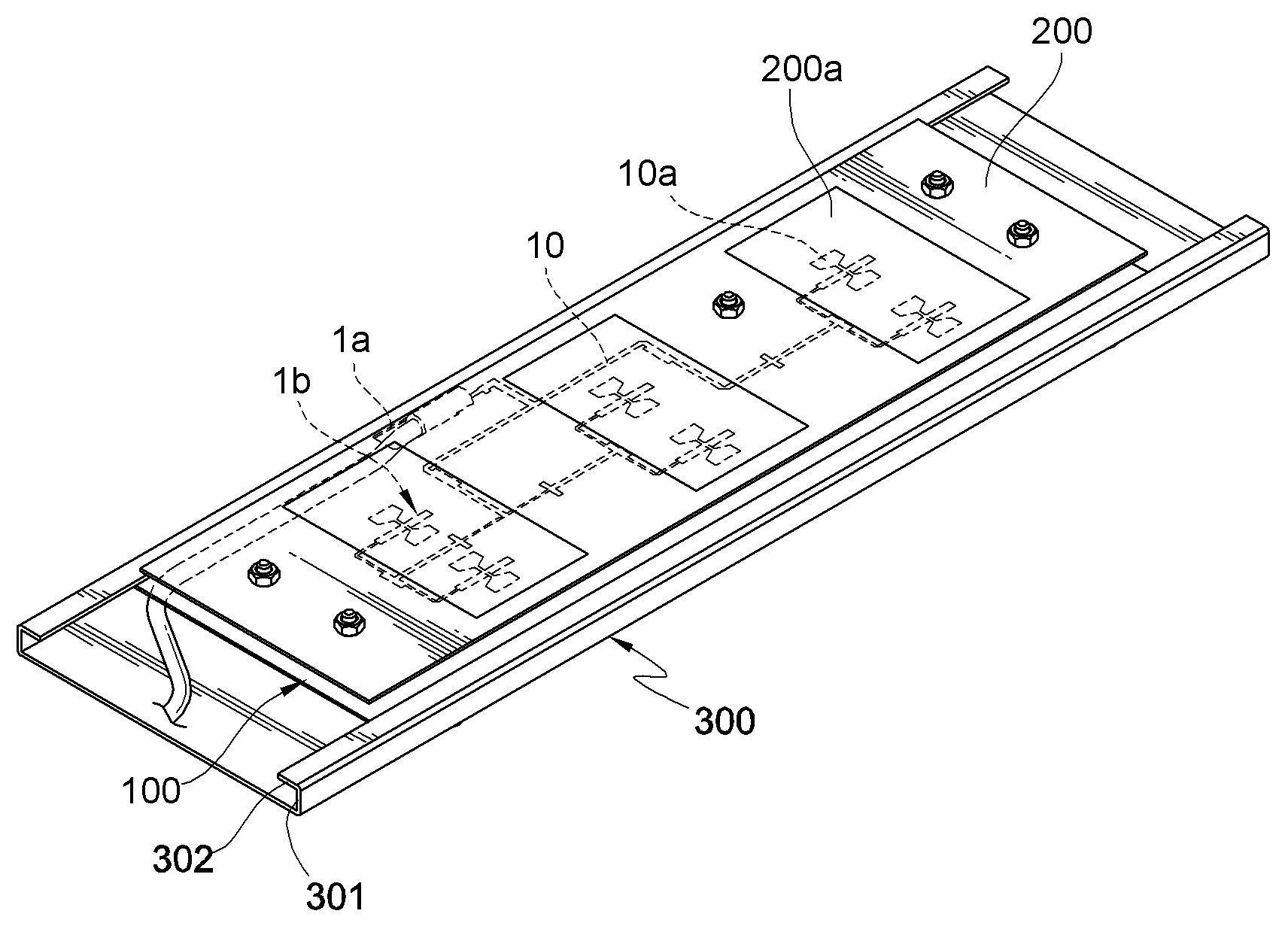
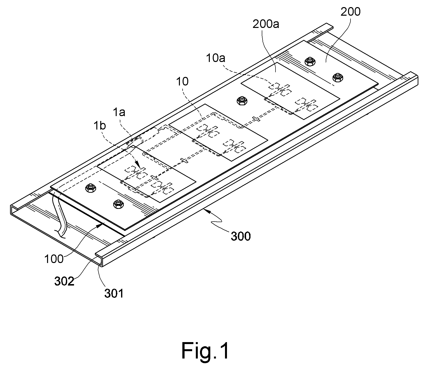
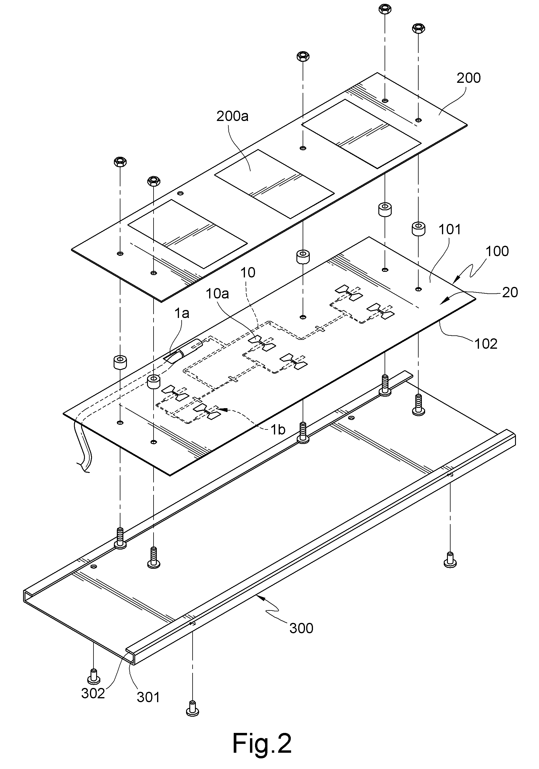
[0033]FIG. 1 is a schematic view of a first embodiment of the present invention. FIG. 2 is an exploded view of the first embodiment of the present invention. For the convenience of illustration, referring to FIG. 2, a slot-coupled microstrip antenna includes a first substrate 100, a second substrate 200, and a support base 300.

[0034]The first substrate 100 has a first surface 101 and a second surface 102. A ground surface 20 is formed on the first surface 101, and a feeding network 10 is formed on the second surface 102. Slots 10a are formed on the ground surface 20, and an embodiment of the slots 10a may be H-shaped, but also can be in a geometrical shape such as a rectangle, square, and round. Microstrip antennae 200a are formed on a plane of the second substrate 200 with a back towards the first substrate 100. The first substrate 100 is generally a printed circuit board (PCB). Certainly, other types of substrates are also applicable. Moreover, the first substrate 100 may be a har...


PUM


Abstract

A slot-coupled microstrip antenna includes a first substrate, a second substrate, and a support base. The first substrate having a first surface and a second surface, in which a ground surface that is formed on the first surface, and a plurality of slots are formed on the ground surface. A feeding network is formed on the second surface. A plurality of antenna corresponding to the slots are formed on the second substrate disposed above the first surface. The support base having two fillisters at two side of the support base. The design of slot structure often has adverse influence on cross polarization and a front-to-back ratio of antenna radiation. The support base having two fillisters of the slot-coupled microstrip antenna can effectively inhibit the influence on the cross polarization and raise the front-to-back ratio from the slots.

Description

BACKGROUND OF THE INVENTION[0001]1. Field of Invention[0002]The present invention relates to a microstrip antenna, and more particularly to a slot-coupled microstrip antenna.[0003]2. Related Art[0004]With the development of wireless communication technology, microstrip antenna technology has become the most rapidly developing one in the antenna field. The microstrip antennae have advantages of small size and low weight, and feature low bandwidth and low gain.[0005]In a normal microstrip antenna design, the method of coupling power into a radiation element of the antenna is roughly classified into a direct-feed mode and an indirect-feed mode. The direct-feed mode uses a coaxial cable or a microstrip line to connect a signal transmission line and the radiation element of the antenna; the indirect-feed mode applies an electromagnetic coupling principle to transfer the power transmission between a signal feeding line and the radiation element of the antenna. Generally speaking, the indi...

Claims


Application Information

Patent Timeline
IPC IPC(8): H01Q13/10H01Q9/04
CPCH01Q9/0407H01Q21/08H01Q21/0081H01Q9/0457
Inventor JENG, JR-REN
Owner SMARTANT TELECOMM
Why Eureka
Try Eureka