Antenna

a small antenna and antenna technology, applied in the direction of antennas, non-resonant long antennas, antenna details, etc., can solve the problems of low gain in a high frequency band, difficult to achieve an antenna of small size and high gain, and achieve the effect of improving the gain of the antenna and miniaturizing the antenna

Inactive Publication Date: 2009-05-21
NOF CORP +2
View PDF7 Cites 26 Cited by
  • Summary
  • Abstract
  • Description
  • Claims
  • Application Information

AI Technical Summary

Benefits of technology

[0009]The antenna according to the present invention has following effects due to the above-described configuration. According to the present invention, an adverse influence by a mitigation loss caused by the magnetic powd...

Problems solved by technology

However, in the case where the mixture amount of magnetic powder is actually increased, there arises a problem of a phenomenon of a decrease in gain in a high fre...

Method used


Image

  • Antenna
  • Antenna
  • Antenna

Examples


first embodiment

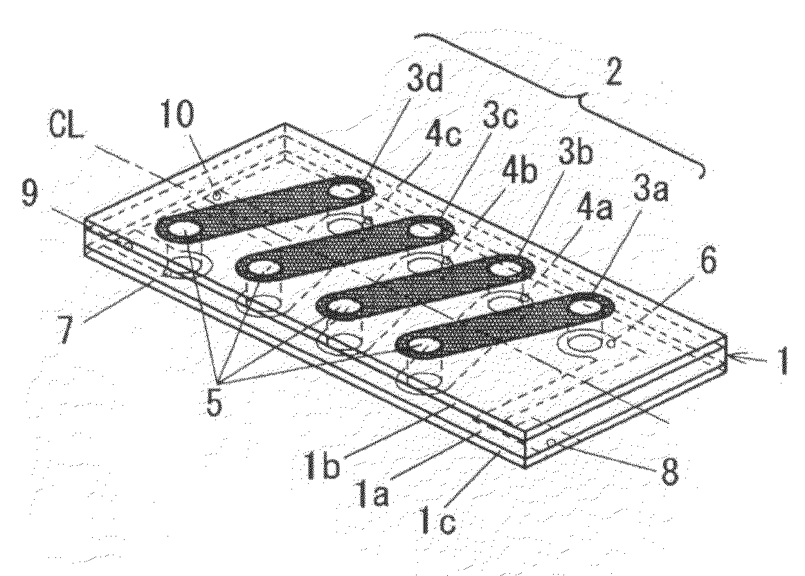
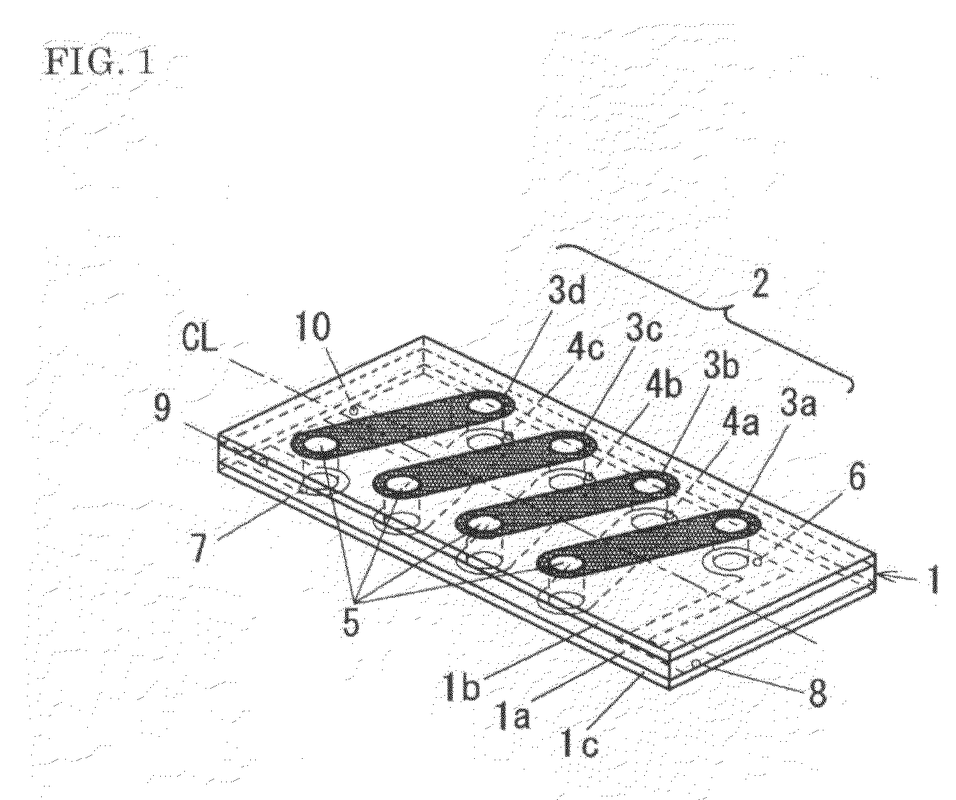
[0029]FIGS. 1 to 3 show a structure of an antenna of a first embodiment according to the present invention.

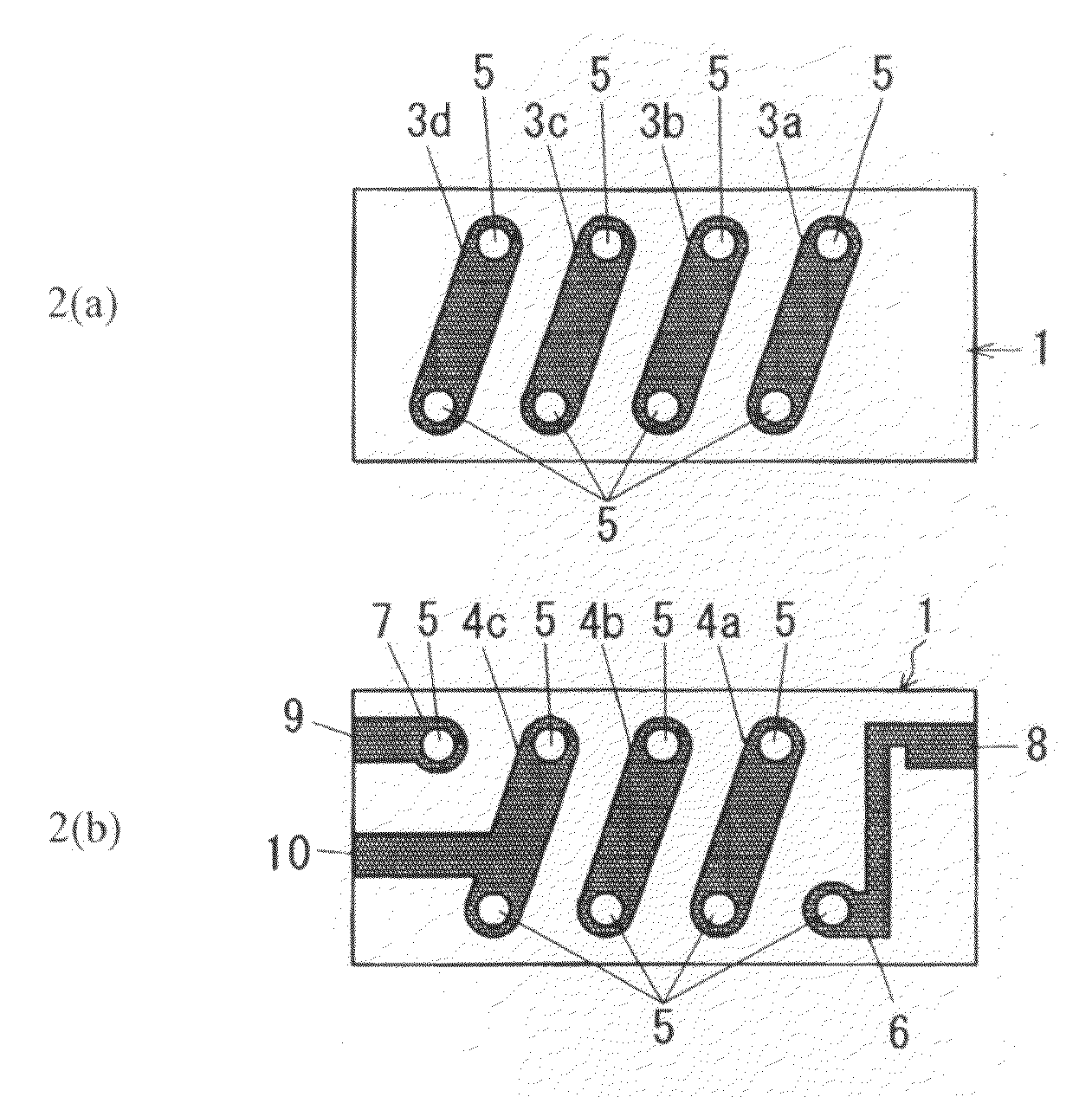
[0030]FIG. 1 is a perspective view showing an antenna; FIGS. 2(a) and 2(b) are views showing the front surface and back surface of the antenna shown in FIG. 1, wherein FIG. 2(a) is a view showing the front surface whereas FIG. 2(b) is a view showing the back surface.

[0031]Reference numeral 1 denotes a core having a laminate structure, in which a first resin layer 1a having magnetic powder mixed therein is formed as a middle layer, and a second resin layer 1b and a third resin layer 1c, which have no magnetic powder mixed therein are formed to sandwich the first resin layer 1a therebetween. The core 1 will be described in detail later.

[0032]Reference numeral 2 denotes a coil conductor constituting the following conductor pattern. On the front surface of the core 1 are formed four conductor patterns 3a to 3d as first conductor patterns. Each of the conductor patterns 3a to 3d is ...

second embodiment

[0045]Next, an antenna of a second embodiment according to the present invention will be described below.

[0046]FIG. 7 shows a core structure used in an antenna of the second embodiment according to the present invention.

[0047]A core 1A shown in FIG. 7 has a constant thickness as a whole; however the thickness of each of first, second, and third resin layers 1d, 1e, and 1f is linearly varied. Specifically, at a right side of the core 1A, the first resin layer 1d is thinly formed while the second and third resin layers 1e and 1f are thickly formed, whereas at a left side of the core 1A, the first resin layer 1d is thickly formed while the second and third resin layers 1e and 1f are thinly formed. The thickness of each of the first, second, and third resin layers 1d, 1e, and 1f is gradually varied from right to left of the core 1A in linear manner.

third embodiment

[0048]Next, an antenna of a third embodiment according to the present invention will be described below.

[0049]FIG. 8 shows a core structure used in an antenna of the third embodiment according to the present invention.

[0050]A core 1B shown in FIG. 8 includes: a first core portion 11 of a single layer structure including a resin layer 1g having magnetic powder mixed therein only at a left half; and the second core portion 12 of a laminate structure including a first resin layer 1h having the magnetic powder mixed therein as a middle layer at a right half, and a second resin layer 1i and a third resin layer 1j, both of which are made of a resin only to sandwich the first resin layer 1h therebetween in a thickness direction.


PUM


Abstract

There is provided an antenna whose outside shape can be miniaturized while maintaining a gain at a desired level with respect to a radio wave of a wide frequency range. The antenna is configured by using a core of a laminate structure. The core is a plate of a rectangular outside shape, configured to have a laminate structure including each of first, second and third resin layers. The first resin layer has magnetic powder mixed therein and formed as a middle layer, and the second resin layer and the third resin layer made of resin only without magnetic powder mixed therein are formed to sandwich the first resin layer therebetween. In the core of the laminate structure, it is preferable to use a polymer resin for each of the resin layers, and to use soft ferrite powder as the magnetic powder.

Description

BACKGROUND OF THE INVENTION[0001]The present invention relates to a structure of a small antenna and, more particularly, to an antenna having high gain and formed in a size allowing it to be equipped in mobile terminal device.[0002]In recent years, there has appeared a mobile terminal device, which singly receives radio waves of wide frequencies including FM radio broadcasting and television broadcasting from VHF band to UHF band, or the wide frequency range further including mobile radio communications in a high frequencies of UHF band, for example. In order to receive the radio waves of the wide frequencies, a wideband antenna capable of handling each of signal frequencies is naturally needed. However, a wavelength of a radio wave in the VHF band is several meters, whereas a wavelength of a radio wave in the UHF band is several tens centimeters. Therefore, in the case where antennas capable of singly coping with the two frequency bands of the UHF and VHF are fabricated to be equip...

Claims


Application Information

Patent Timeline
IPC IPC(8): H01Q7/08
CPCH01Q1/362H01Q1/38H01Q11/08H01Q7/08H01Q7/06
Inventor SONODA, KENSAKUKAN, RIKIYASHIROTA, KENICHIKOIKE, KIYOSHI
Owner NOF CORP
Why Eureka
Try Eureka