Method for transmitting control signals and pixel data signals to source drives of an LCD

a liquid crystal display and control signal technology, applied in the direction of electric digital data processing, instruments, computing, etc., can solve the problems of large power consumption, more serious emi (electromagnetic interference) effect, and higher fabrication cost, so as to achieve the effect of greatly reducing the total number of input signals for each source driver

Inactive Publication Date: 2009-05-21
HIMAX TECH LTD
View PDF3 Cites 3 Cited by
  • Summary
  • Abstract
  • Description
  • Claims
  • Application Information

AI Technical Summary

Benefits of technology

[0007]An objective of the present invention is to provide a method for transmitting control signals and pixel data signals to source drivers of a liquid crystal display in which control signals and

Problems solved by technology

Furthermore, increasing the bits of the pixel value will necessitates more wire lines and therefore result in

Method used


Image

  • Method for transmitting control signals and pixel data signals to source drives of an LCD
  • Method for transmitting control signals and pixel data signals to source drives of an LCD
  • Method for transmitting control signals and pixel data signals to source drives of an LCD

Examples


Embodiment Construction

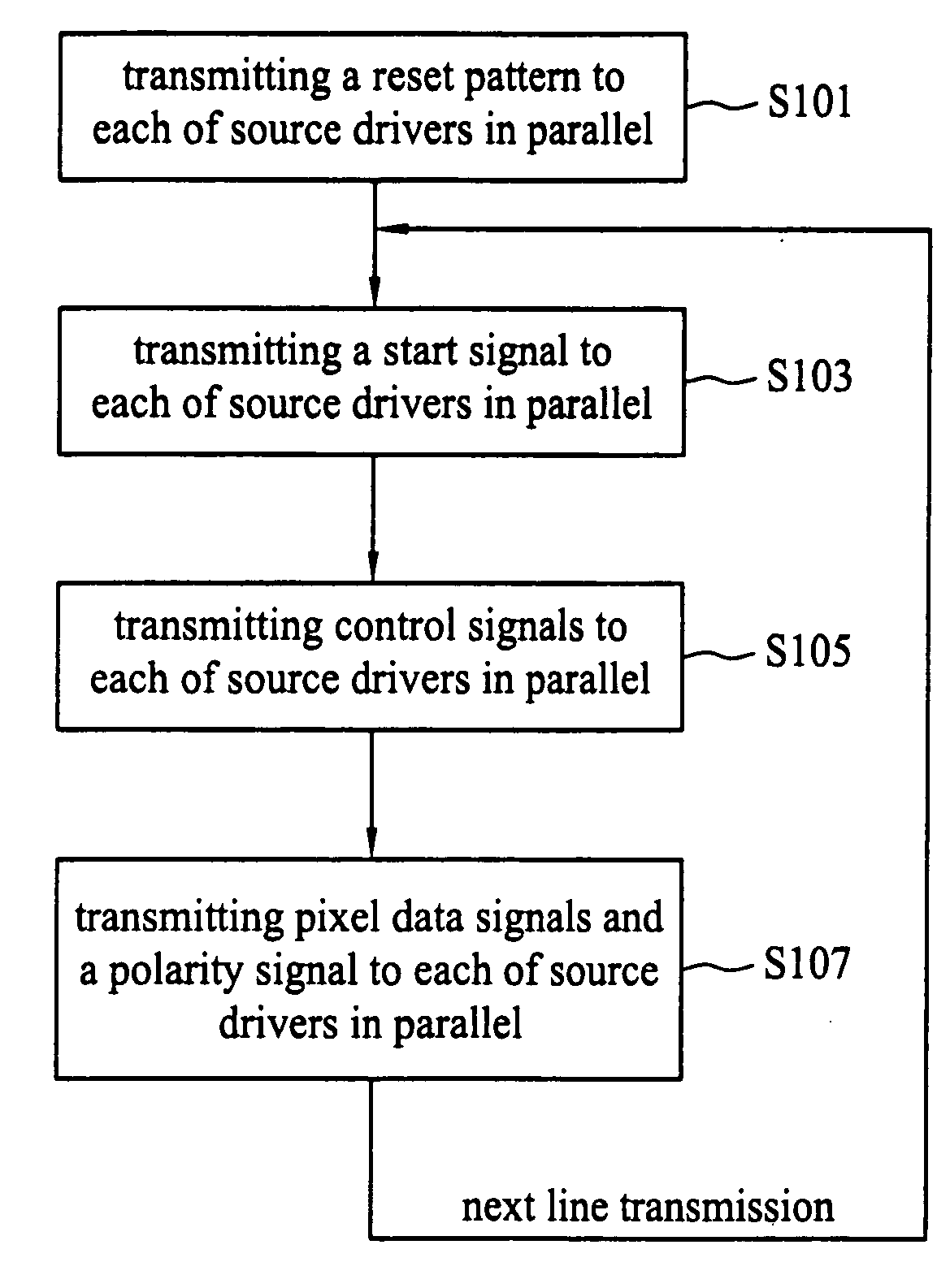
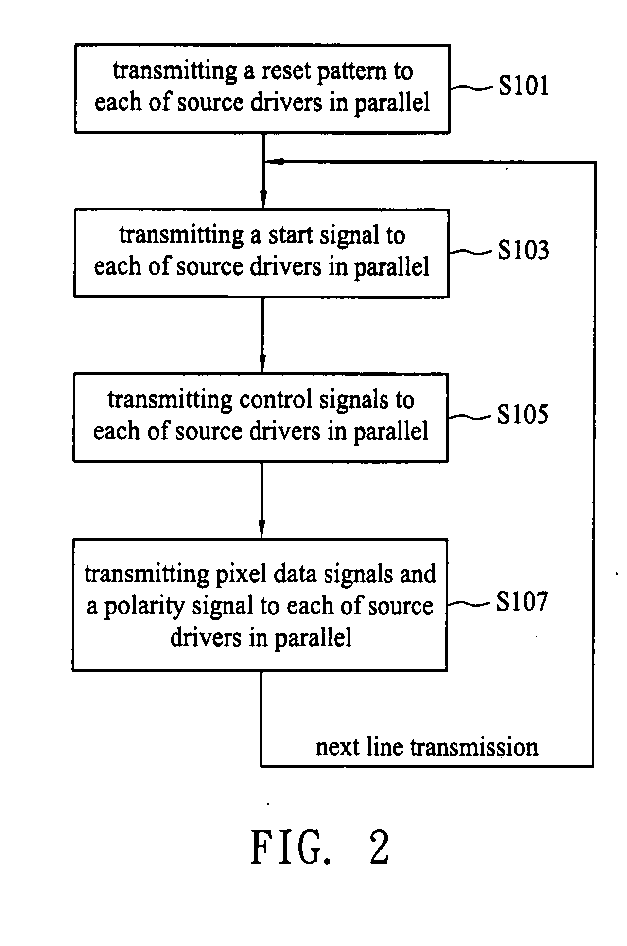
[0017]FIG. 2 is a flow chart showing a transmission method for control signals and pixel data signals in accordance with a preferred embodiment of the invention. Referring to Step S101, a reset pattern is transmitted to each of the source drivers of an LCD in parallel when the LCD is turned on or the data temporally stored in the source drivers need to be deleted. Afterward, a start signal is transmitted to each of source drivers in parallel for informing the source drivers of the start of a new line transmission, as shown in Step S103. In consequential Step 105, the control signals are transmitted to each of the source drivers in parallel. Final, the pixel data signals for driving a column line and a polarity signal are transmitted to each of the source drivers in parallel, wherein the polarity signal indicates whether the pixel data signals are inverted, and the polarity signal and the start signal are transmitted through a same channel, as shown in Step 107.

[0018]FIG. 3 is a diag...


PUM


Abstract

A method is applicable to an LCD for transmitting control signals and pixel data signals to source drivers. First, control signals are transmitted to each of source drivers in parallel during a control period. Pixel data signals for driving a horizontal pixel line are transmitted to each of the source drivers in parallel during plural pixel data periods. The control signals and the pixel data signals are transmitted through a same set of channels connected to each of the source drivers according to a pixel clock signal.

Description

BACKGROUND OF THE INVENTION[0001]1. Field of the Invention[0002]The present invention relates to a method for transmitting control signals and pixel data signals to source drivers of a liquid crystal display (LCD), and more particularly relates to a data transmission method between a timing controller and source drivers of a LCD.[0003]2. Description of the Related Art[0004]FIG. 1 illustrates a circuitry of a conventional LCD. The conventional LCD includes a group of source drivers 13, a group of gate drivers 14, an LCD panel 11 and a timing controller 12. As shown in FIG. 1, a video processing system 15 transmits RGB data and control signals including a clock signal, a horizontal synchronizing signal and a vertical synchronizing signal to a timing controller 12. The timing controller 12 rearranges and transfers the RGB data, and outputs essential control signals to the source driver 13.[0005]An RSDS (reduced swing differential signaling) interface circuit or TTL (single edge of tran...

Claims


Application Information

Patent Timeline
IPC IPC(8): G09G3/36
CPCG06F3/14G09G3/2096G09G2330/06G09G3/3688G09G2310/08G09G3/3614
Inventor CHANG, YU JUI
Owner HIMAX TECH LTD
Why Eureka
Try Eureka