Material measurement system for obtaining coincident properties and related method

a measurement system and coincident property technology, applied in the field of process control systems, can solve the problems of affecting the quality of paper produced, sb>3/b> together are generally bulky in size, and cannot be easily fitted, or placed

Inactive Publication Date: 2009-05-21
HONEYWELL ASCA INC
View PDF9 Cites 38 Cited by
  • Summary
  • Abstract
  • Description
  • Claims
  • Application Information

AI Technical Summary

Benefits of technology

[0016]The THz emitter and receiver can be combined in a single sensor module. In this embodiment, the system can further comprise a scanner coupled to the sensor module for moving the sensor to obtain the properties of the sheet material from a plurality of sample locations across a width of the system. The analyzer can be operable to simultaneously measure two or more of basis weight, moisture, and caliper (thickness), composition, and fiber orientation at the sample location.
[0017]A controlled system or forming material comprises a material making system including a plurality of actuators. A control system is operatively coupled to the material making system comprising a THz generator including at least one laser source for emitting optical pulses, the optical pulses coupled to a THz emitter operable for emitting pulsed THz radiation at a sample location on material being processed by the material masking system. A receiver is operable to receive the optical pulses and to detect reflected or transmitted THz radiation from the sample location synchronously with the optical pulses and provide electrical detection signals. Synchronizing optics is operable to receive the optical pulses from the laser and provide the optical pulses to both the receiver and THz emitter. A controller comprising at least one processor receives the electrical detection signals and provides a processed electrical detection signal. An analyzer is operable to determine at least one property of the material from the processed electrical detection signal. The controller is operably linked to control operation of the material making system using at least one of the plurality of actuators based on the property.
[0018]In one embodiment the material making system can comprise a paper making system comprising in serial connection a press section including at least one actuator arranged to control mechanical water removal from wetstock material to begin formation of a sheet material, a dryer section including at least one actuator arranged to control evaporative drying of the sheet material, a calendering stack including at least one actuator to control compressive pressure to the sheet material, and a take-up reel for producing a continuous roll of the sheet material.
[0019]A method for in-situ quality control of material processed by a manufacturing system, comprises the steps of directing THz radiation at a sample location on material being processed by the manufacturing system, measuring reflected radiation or transmitted radiation from the sample location and generating electrical detection signals therefrom, transmitting the electrical detection signals to a remotely located controller comprising at least one processor for receiving the electrical detection signals, and providing a processed electrical detection signal. At least one property of the material is determined from the processed electrical detection signal, and at least one process parameter is automatically modified based on the property. The at least one property can comprises a plurality of the properties, wherein the plurality of properties are determined from coincident measuring of the reflected radiation or transmitted radiation from a single sample location. The determining step can comprise generating a time-domain spectroscopy (TDS) spectrum from the processed electrical detection signal.
[0020]The sample location can be within a wet-zone of the system. The Wet-zone is defined herein as an area where there is more water than fiber (by weight). Generally, dry end measurements refer to measurements where there is less water than fiber, such as less than 20% moisture.

Problems solved by technology

Many factors influence the rate at which water is removed which ultimately affects the quality of the paper produced.
The sensors S1, S2 and S3 of the scanning device 17 are on the dry end because their on-board electronics may not operate properly, or can be damaged, in the high heat and moisture environments at the “wet-end”.
Furthermore, the sensors S1, S2 and S3 together are generally bulky in size and cannot easily fit, or be placed, at strategic measuring locations within the “wet-end”.
While “dry-end” measurement control has provided significant benefits to the paper manufacturing industry, it does have certain limitations.
Although the sensors are proximate to one another, they are generally unable to measure discrete quality properties at a particular location simultaneously.
Moreover, the scanning device may not be able to take measurements at different points in the process, for example, at the “wet-end” where extremely high temperature and moisture conditions exist, which as previously noted can result in damage to the receiving sensors (S1, S2 and S3).
The “dry-end” measurements are generally inadequate for capturing the changes of the paper at different process points in the paper-making process.
Such incomplete process measurements can result in manufacturing deficiencies, such as lower quality and higher cost.
Moreover, when measurements taken at the “dry-end” in the paper-making process are used to estimate measurements at the “wet-end”, errors can be introduced as a result of the estimation.
Errors can also be generated due to machine speed inaccuracies, different measurement spot sizes, non-linear shrinkage and / or sheet wander.
Furthermore, traditional scanning devices operating at the “dry-end” have difficulty separating densification in the press section from that in the dryer sections, and thus cannot generally provide accurate measurements of paper density.
Each property under observation can invoke various degrees of control complexity.
Such control could otherwise be problematic if web wander and non-linear shrinkage change the mapping of measurement zones to actuator zones were not taken into account at the “wet-end”.

Method used


Image

  • Material measurement system for obtaining coincident properties and related method
  • Material measurement system for obtaining coincident properties and related method
  • Material measurement system for obtaining coincident properties and related method

Examples


Embodiment Construction

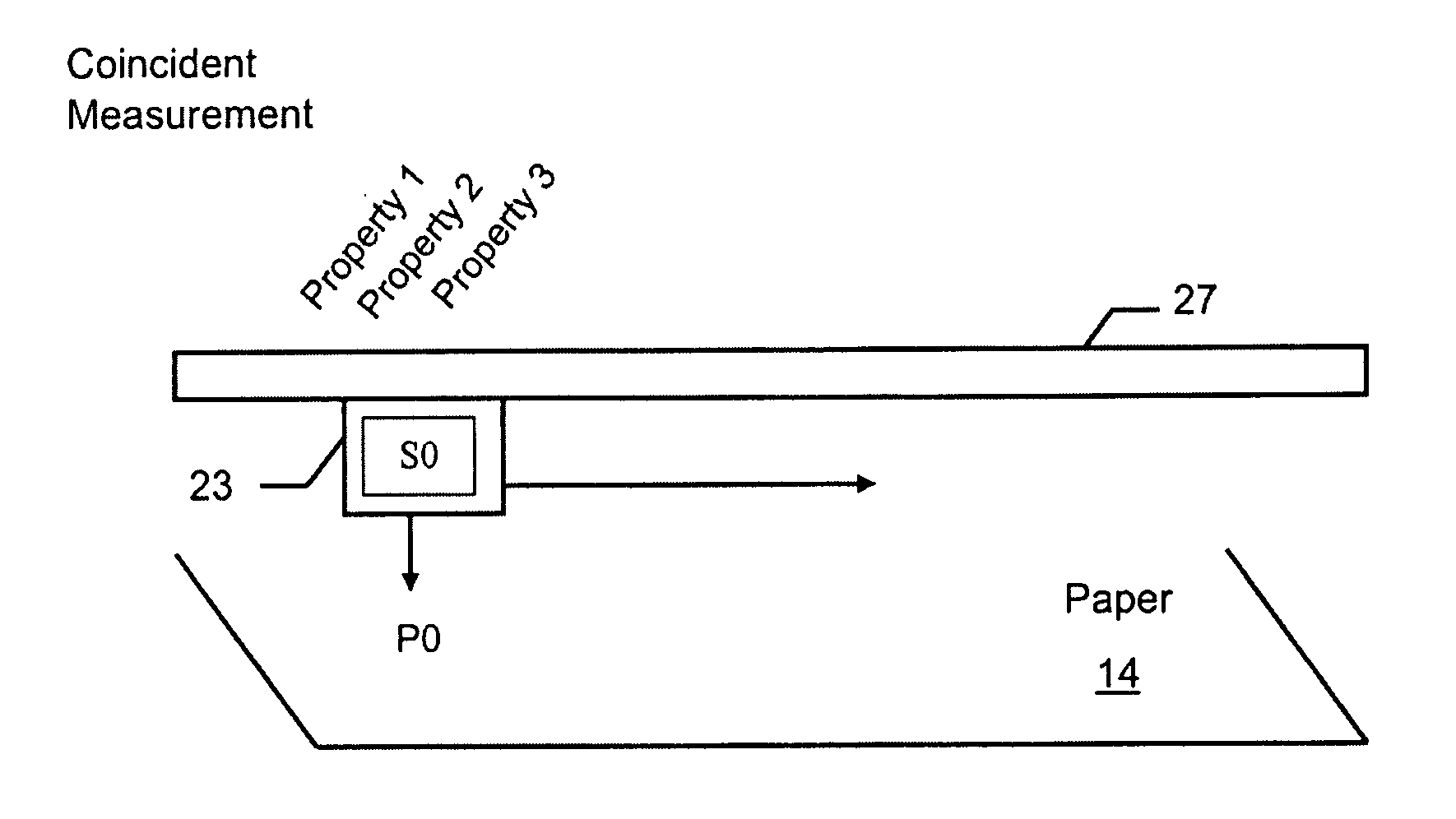
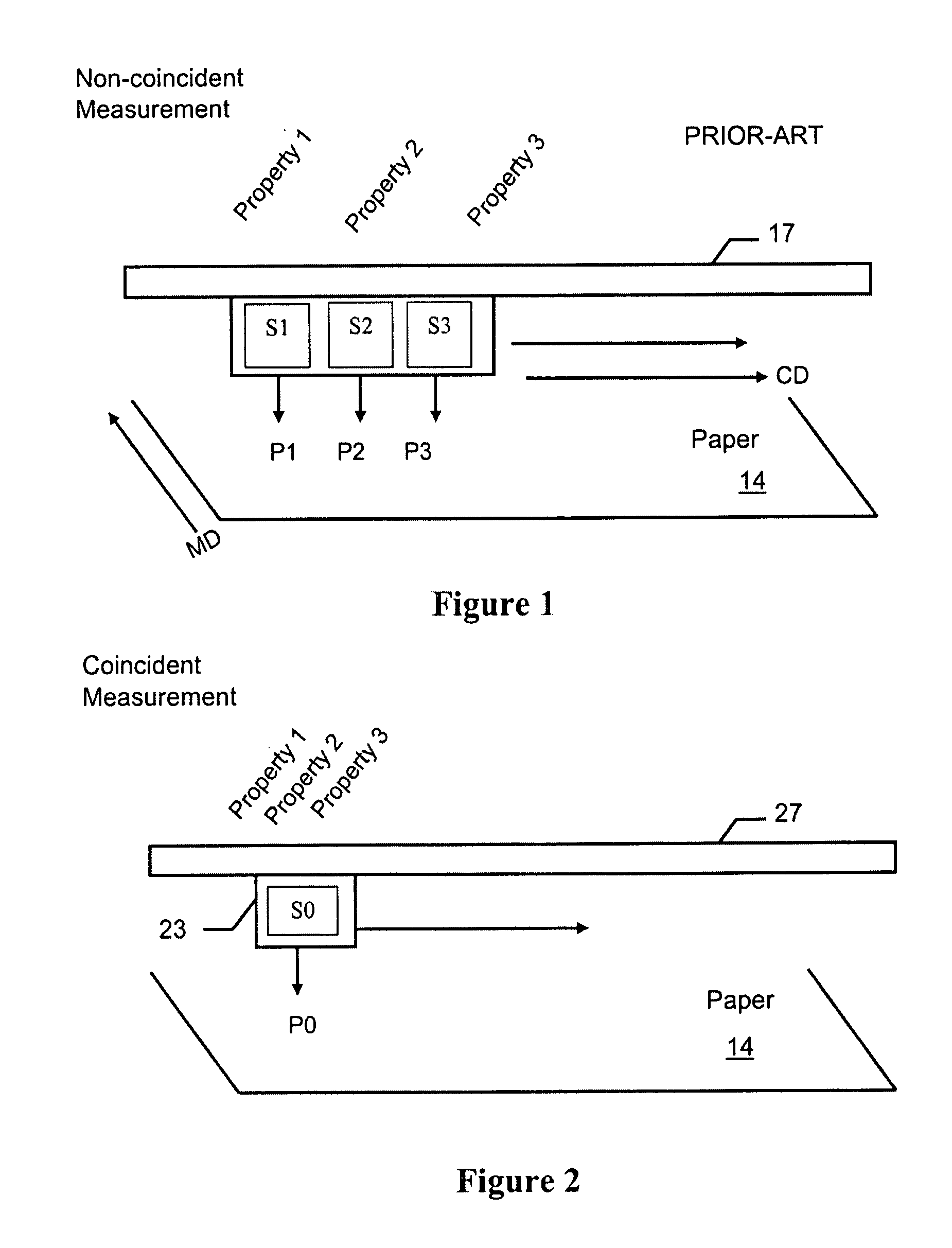
[0028]Referring FIG. 2, an exemplary sensor device 23, according to an embodiment of the invention for simultaneously measuring at least one property, and generally a plurality of properties, of a material, such as paper 14, is shown. In one arrangement, the sensor device 23 can be coupled to a scanner 27 operable to move the sensor device 23 across the width of the paper, transverse to the paper translation path. In another arrangement, the sensor device 23 can remain at a fixed location along the length of the scanner 27 for obtaining fixed point measurements. In the fixed embodiment, the mounting device for the sensor generally does not span the entire width of the machine, but generally projects a meter or two from one edge. The sensor device 23 can obtain a plurality of property measurements of the paper 14 coincidently; that is, at the same paper location and at the same time. For example, the sensor device 23 can measure Property 1, Property 2, and Property 3, such as basis w...


PUM


Abstract

A material measurement system (500) includes a THz generator including at least one laser source (111) for emitting optical pulses, the optical pulses coupled to a THz emitter (51) operable for emitting pulsed THz radiation at a sample location on material while being processed (14) by a manufacturing system. A receiver (52) is operable to receive the optical pulses and to detect reflected or transmitted THz radiation from the sample location (14) synchronously with the optical pulses and provide electrical detection signals. Synchronizing optics (112, 113, 114) is operable to receive the optical pulses from said laser and provide the optical pulses to both the receiver (52) and the THz emitter (51). A controller (25) includes at least one processor (87) for receiving the electrical detection signals and providing a processed electrical detection signal, and an analyzer (88) operable to determine at least one, and generally a plurality of properties of the material from the processed electrical detection signal.

Description

FIELD OF THE INVENTION[0001]The invention generally relates to process control systems and more specifically to Terahertz spectroscopy-based measurement and control systems for controlling the quality of manufactured materials, such as paper.BACKGROUND[0002]Processing facilities, such as paper-making mills and material manufacturing mills, are typically managed using process control systems and quality control systems (QCS). Valves, pumps, motors, heating / cooling devices, and other industrial equipment and electronics typically perform actions needed to process materials in the processing facilities. Among other functions, the process control systems and QCS often manage the use of the industrial equipment in the processing facilities.[0003]The process control system may comprise a Distributed Control Systems (DCS). The DCS is typically connected to and works in coordination with the QCS which generally include devices for measuring attributes of the product being manufactured (e.g....

Claims


Application Information

Patent Timeline
Patent Type & Authority Applications(United States)
IPC IPC(8): G01C3/08
CPCD21G9/0036D21G9/0045G01B11/06G01N21/3563G01N21/3581G01N21/86G01N21/3559G01N21/3554
Inventor MACHATTIE, ROSSHARAN, FRANK M.DUCK, GRAHAM I.GORDON, DANJEZ, DAVID R.
Owner HONEYWELL ASCA INC
Why Eureka
Try Eureka