Diffraction Grating With a Spatially Varying Duty-Cycle

a duty-cycle and diffraction grating technology, applied in the field of optics, can solve the problems of not being able to easily miniaturize, heavy crt display, heavy, etc., and achieve the effect of reducing the cost of operation, and improving the quality of operation

Inactive Publication Date: 2009-05-21
MIRAGE INNOVATIONS LTD
View PDF68 Cites 147 Cited by
  • Summary
  • Abstract
  • Description
  • Claims
  • Application Information

AI Technical Summary

Problems solved by technology

Unless a person is long-sighted, he may not be able to view a sharp image at a closer distance.
The CRT displays are heavy, bulky and not easily miniaturized.
The active matrix panel uses a transistor to control each pixel, and is more expensive.
Small size real image displays have a relatively small surface area on which to present a real image, thus have limited capability for providing sufficient information to the user.
In other words, because of the limited resolution of the human eye, the amount of details resolved from a small size real image might be insufficient.
For example, such displays have suffered from being too heavy for comfortable use, as well as too large so as to be obtrusive, distracting and even disorienting.
These defects stem from, inter alia, the incorporation of relatively large optics systems within the mounting structures, as well as physical designs which fail to adequately take into account important factors as size, shape, weight, etc.
A common problem to all types of holographic optical elements is their relatively high chromatic dispersion.
This is a major drawback in applications where the light source is not purely monochromatic.
Another drawback of some of these displays is the lack of coherence between the geometry of the image and the geometry of the holographic optical element, which causes aberrations in the image array that decrease the image quality.
New designs, which typically deal with a single holographic optical element, compensate for the geometric and chromatic aberrations by using non-spherical waves rather than simple spherical waves for recording; however, they do not overcome the chromatic dispersion problem.
Moreover, with these designs, the overall optical systems are usually very complicated and difficult to manufacture.
Furthermore, the field-of-view resulting from these designs is usually very small.
Upatnieks, however, does not teach how to control the intensity profile of the optical output.
However, the diffractive collimating element of Friesem et al. is known to narrow spectral response, and the low chromatic sensitivity at spectral range of ±2 nm becomes an unacceptable sensitivity at ±20 nm or ±70 nm.
As a result, the optical output across the grating is not uniform.

Method used


Image

  • Diffraction Grating With a Spatially Varying Duty-Cycle
  • Diffraction Grating With a Spatially Varying Duty-Cycle
  • Diffraction Grating With a Spatially Varying Duty-Cycle

Examples


example 1

Non-Uniform Duty Cycle

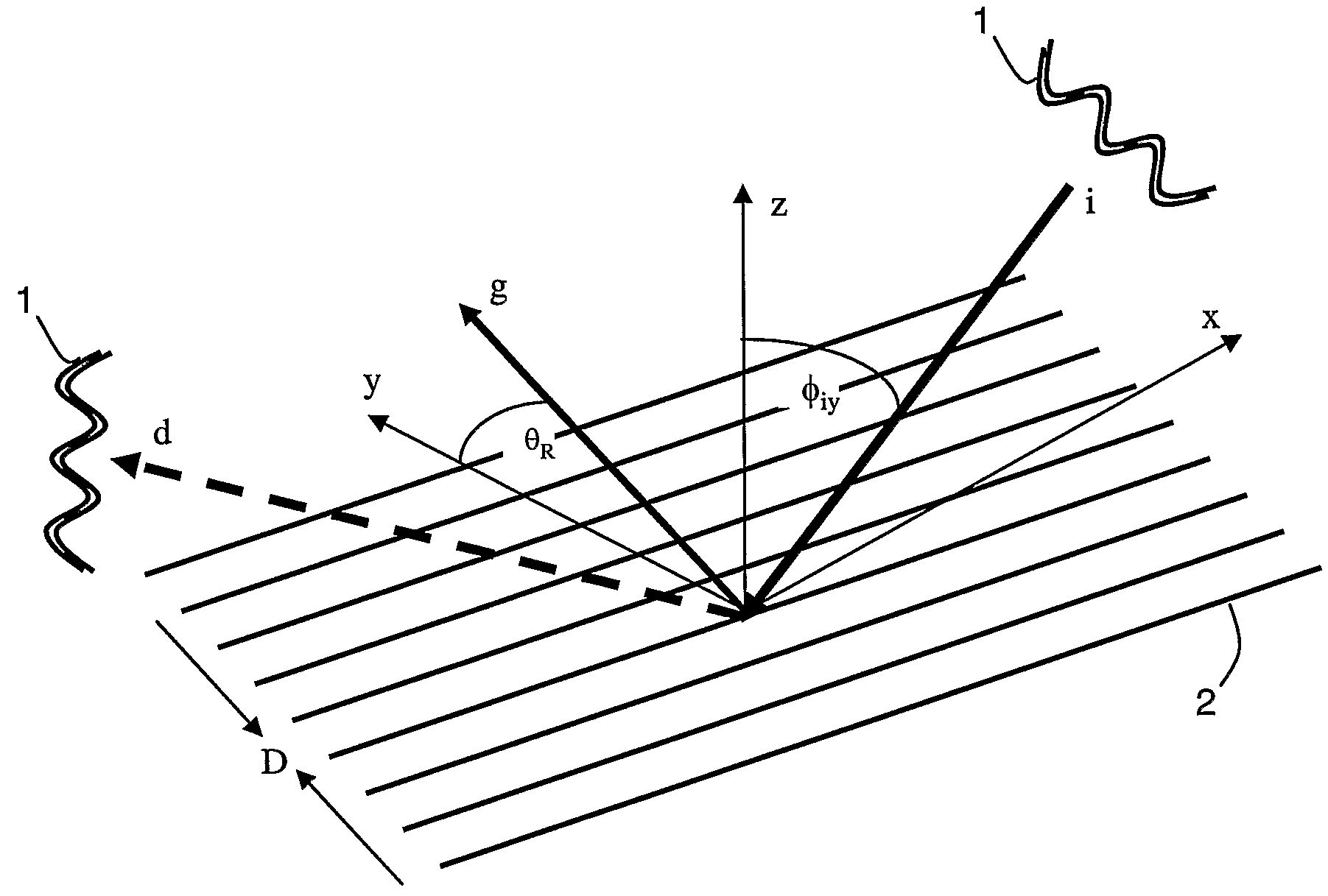
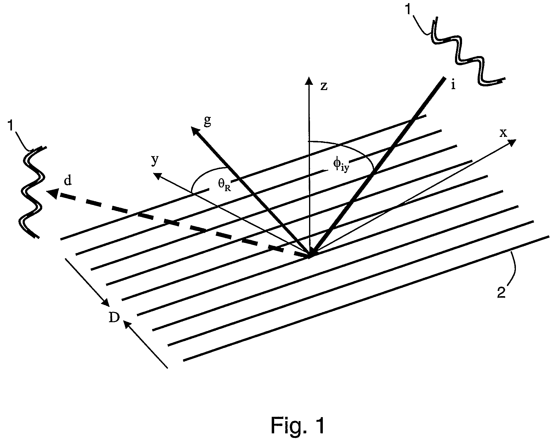
[0177]FIGS. 12a-d show numerical calculations of the diffraction efficiency of a grating as a function of the duty cycle, for impinging angles φiy of 50° (FIGS. 12a-b) and 55° (FIGS. 12c-d), and modulation depths 6 of 150 nm (FIGS. 12a and 12c) and 300 nm (FIGS. 12b and 12d). The different curves in FIGS. 12a-d correspond to wavelengths of 480 nm (solid line), 540 nm (dashed line) and 600 nm (dot-dash line). The calculations were based on the Maxwell equations, for 455 nm period grating formed in a light transmissive substrate having index of refraction of 1.53.

example 2

Non-uniform Modulation Depth

[0178]FIGS. 13a-b show numerical calculations of the diffraction efficiency of a grating as a function of the modulation depth δ, for impinging angles φiy of 50° (FIG. 13a) and 55° (FIG. 13b), and duty cycle of 0.5. The different curves in FIGS. 13a-b correspond to wavelengths of 480 nm (solid line), 540 nm (dashed line) and 600 nm (dot-dash line). The calculations were based on the Maxwell equations, for 455 nm period grating formed in a light transmissive substrate having index of refraction of 1.53.

[0179]As shown in FIGS. 13-a-b, the diffraction efficiency increases with increasing δ up to modulation depth of about 200-250 nm. Above about 250 nm, the diffraction efficiency decreases with increasing δ up to modulation depth of about 400-500 nm.

[0180]It is appreciated that certain features of the invention, which are, for clarity, described in the context of separate embodiments, may also be provided in combination in a single embodiment. Conversely, var...


PUM


Abstract

A diffractive optical element is disclosed. The optical element comprises a grating having a periodic linear structure in at least one direction. The linear structure is characterized by non-uniform duty cycle selected to ensure non-uniform diffraction efficiency.

Description

FIELD AND BACKGROUND OF THE INVENTION[0001]The present invention relates to optics, and, more particularly, to a method device and system for transmitting light at predetermined intensity profile.[0002]Miniaturization of electronic devices has always been a continuing objective in the field of electronics. Electronic devices are often equipped with some form of a display, which is visible to a user. As these devices reduce in size, there is an increase need for manufacturing compact displays, which are compatible with small size electronic devices. Besides having small dimensions, such displays should not sacrifice image quality, and be available at low cost. By definition the above characteristics are conflicting and many attempts have been made to provide some balanced solution.[0003]An electronic display may provide a real image, the size of which is determined by the physical size of the display device, or a virtual image, the size of which may extend the dimensions of the displ...

Claims


Application Information

Patent Timeline
Patent Type & Authority Applications(United States)
IPC IPC(8): G02B27/44G02B5/18
CPCG02B5/1866G02B5/32G02B6/0016G02B6/0038G02B6/2848G02B2027/0178G02B27/0172G02B2027/011G02B2027/0123G02B2027/0132G02B2027/0174G02B27/0081G02B27/4272
Inventor ITZKOVITCH, MOTINEISTEIN, EYALKONFORTI, NAIM
Owner MIRAGE INNOVATIONS LTD
Why Eureka
Try Eureka