Cpp magneto-resistive element provided with a pair of magnetic layers and nicr buffer layer

a magneto-resistive element and buffer layer technology, applied in the field of magnetic field detecting elements, can solve the problems of significantly low electrical resistance, limiting the degree to which the film thickness of the stack can be reduced, and effectively limited barkhausen noise, etc., to achieve sufficient exchange coupling, increase the electrical resistance, and large the effect of magneto-resistive

Inactive Publication Date: 2009-05-21
TDK CORPARATION
View PDF4 Cites 17 Cited by
  • Summary
  • Abstract
  • Description
  • Claims
  • Application Information

AI Technical Summary

Benefits of technology

[0010]The present invention concerns a CPP magnetic field detecting element having a film configuration in which a stack is provided which includes a pair of magnetic layers whose magnetization directions vary in accordance with the external magnetization, similarly to a conventional free layer, and in which a bias magnetic layer is disposed on the back side of the stack as viewed from the air bearing surface. An object of the invention is to provide a magnetic field detecting element that has the above-mentioned film configuration and that is capable of obtaining both an increase in the electrical resistance and sufficient exchange coupling between the two magnetic layers and that is thereby capable of achieving a large magneto resistive effect while enabling a reduction in the shields gap.
[0012]The inventors of the present application found that by utilizing first and second magnetic layers each having a bcc (body centered cubic) crystalline structure and by disposing a NiCr layer in contact with the first magnetic layer, sufficient exchange coupling can be achieved between the pair of magnetic layers even when a non-magnetic spacer layer that includes an insulating layer or a semiconductor layer, which conventionally can not produce sufficient exchange coupling, is used. This enables both a large magneto resistance ratio and exchange coupling between the pair of magnetic layers, and thereby enables an increase in the electrical resistance. Also, this structure requires neither an antiferromagnetic layer nor a synthetic pinned layer in the stack, and facilitates a reduction in the film thickness of the stack. In this way, it is possible to provide a magnetic field detecting element that has the above-mentioned film configuration and that is capable of achieving a large magneto resistive effect while enabling a reduction in the shields gap.

Problems solved by technology

The free layer is magnetized into a single magnetic domain by the bias magnetic field that is applied from the bias magnetic layers, and as a result, not only linearity of change in electric resistance relative to change in an external magnetic field is enhanced but also the Barkhausen noise can be effectively limited.
However, there is large restriction that results from the film configuration in the conventional CPP-GMR elements.
Despite these advantages of the synthetic pinned layer, however, a CPP-GMR element having a synthetic pinned layer requires many layers, and this leads to limiting the degree to which the film thickness of the stack can be reduced.
In a CPP-GMR element, in which the sense current flows in a direction that is perpendicular to the stack (spin valve film), the stack is usually formed of metal materials, and as a result, has a significantly low electrical resistance.
Low electrical resistance leads to a small change in electrical resistance, and therefore, a large MR ratio can not be obtained.
However, these materials are usually not provided with properties to produce the RKKY interaction.
For example, according to a report, it is known that a non-magnetic spacer layer that is made of MgO and that has a film thickness of 0.6 nm exhibits weak RKKY interaction (exchange coupling constant; 0.26×10⁻⁷ J / cm2), but this exchange coupling constant is not enough to generate sufficient exchange coupling between the two free layers, and therefore, a magneto resistance ratio at a practical level can not be obtained.
Accordingly, it is difficult for a CPP-GMR element using two free layers to obtain both an increase in the electrical resistance and sufficient exchange coupling between the two free layers, and thereby to achieve a large magneto resistance ratio.

Method used


Image

  • Cpp magneto-resistive element provided with a pair of magnetic layers and nicr buffer layer
  • Cpp magneto-resistive element provided with a pair of magnetic layers and nicr buffer layer
  • Cpp magneto-resistive element provided with a pair of magnetic layers and nicr buffer layer

Examples


Embodiment Construction

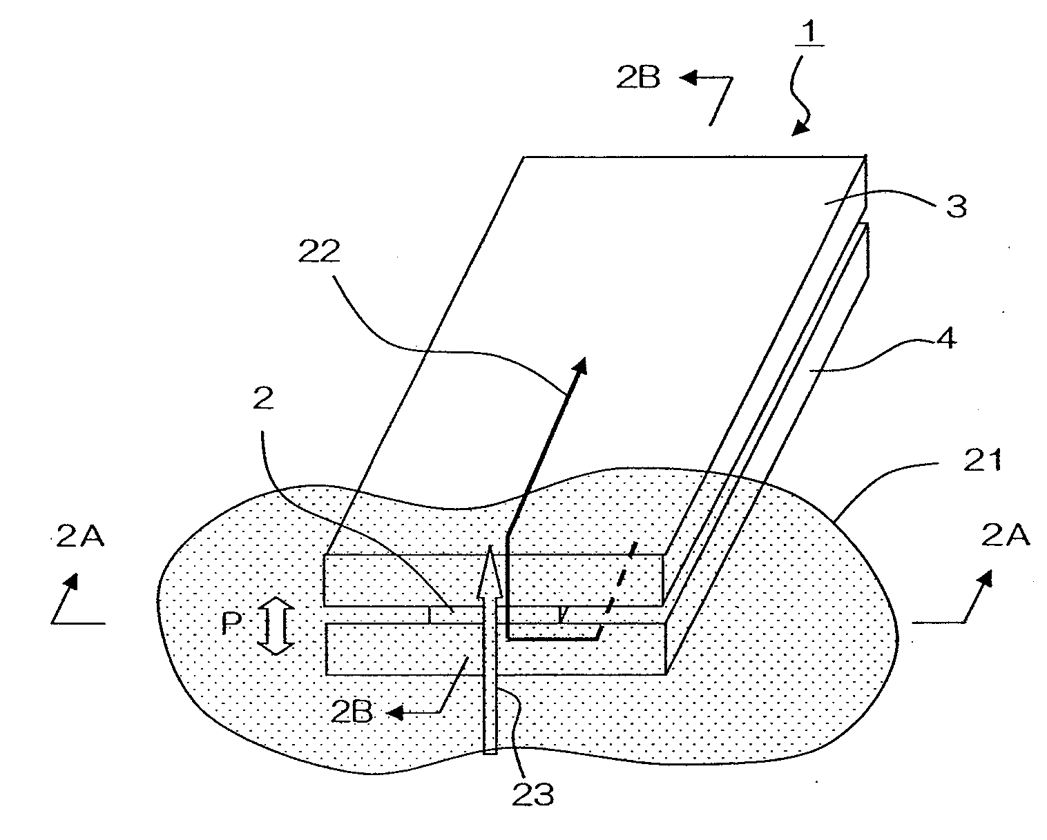
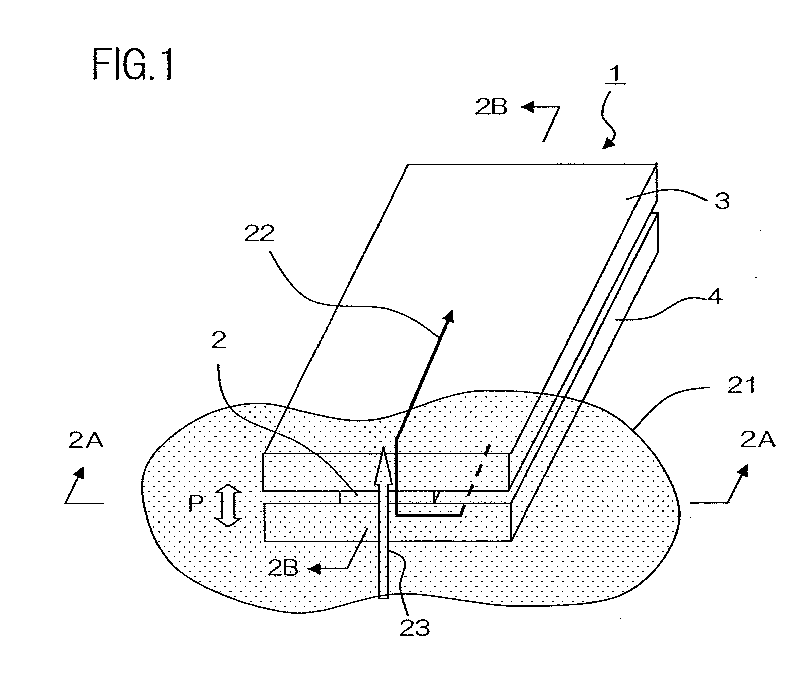
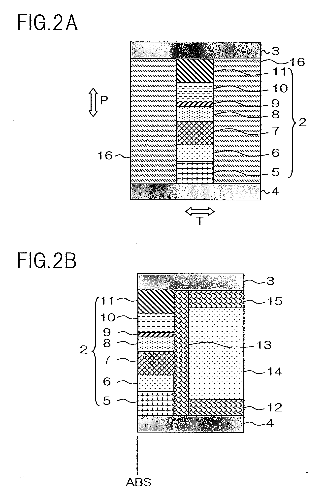
[0025]A preferred embodiment of the present invention will be described below with reference to the accompanying drawings. The magnetic field detecting element of the present embodiment is suitable for use as the read head portion of a thin film magnetic head of a hard disk device. FIG. 1 illustrates a conceptual perspective view of the magnetic field detecting element of the present embodiment. FIG. 2A illustrates a side view of the magnetic field detecting element as seen from direction 2A-2A of FIG. 1, i.e. as seen from the air bearing surface; and FIG. 2B illustrates a sectional view of the magnetic field detecting element cut along line 2B-2B of FIG. 1. The air bearing surface refers to the face of magnetic field detecting element 1 that faces recording medium 21.

[0026]Magnetic field detecting element 1 includes stack 2, upper shield electrode layer 3 and lower shield electrode layer 4 that sandwich stack 2 in the direction of stacking thereof, bias magnetic layer 14 that is ar...


PUM

PropertyMeasurementUnit
thicknessaaaaaaaaaa
thicknessaaaaaaaaaa
thicknessaaaaaaaaaa

Abstract

A magnetic field detecting element has a stack which includes a NiCr layer, a first magnetic layer whose magnetization direction varies in accordance with an external magnetic field, a non-magnetic spacer layer, and a second magnetic layer whose magnetization direction varies in accordance with the external magnetic field, said NiCr layer, said first magnetic layer, said spacer layer and said second magnetic layer being disposed in this order and being arranged in contact with each other, wherein a sense current is adapted to flow in a direction that is perpendicular to a film surface of said stack; and a bias magnetic layer which is disposed on a side of said stack, said side being opposite to an air bearing surface of said stack, wherein said bias magnetic layer is adapted to apply a bias magnetic field to said stack in a direction that is perpendicular to said air bearing surface. Both first and second magnetic layers have bcc crystalline structures, and said non-magnetic spacer layer has a film configuration in which an insulating layer or a semiconductor layer is inserted into a metal layer.

Description

BACKGROUND OF THE INVENTION[0001]1. Field of the Invention[0002]The present invention relates to a magnetic field detecting element, and in particular, to a magnetic field detecting element having a pair of magnetic layers.[0003]2. Description of the Related Art[0004]Giant Magneto-Resistance (GMR) elements are known as a read element that is used for a thin film magnetic head. Conventionally, CIP (Current In Plane)-GMR elements, in which sense current flows parallel with the film surface of the element, have been mainly used, but recently, elements in which sense current flows in a direction that is perpendicular to the film surface of the element have been developed in order to cope with higher recording density. CPP (Current Perpendicular to the Plane)-GMR elements which utilize the GMR effect are known as the latter type.[0005]A CPP-GMR element typically has a stack that includes a magnetic layer whose magnetization direction varies in accordance with an external magnetic field (...

Claims


Application Information

Patent Timeline
Patent Type & Authority Applications(United States)
IPC IPC(8): G11B5/33
CPCB82Y25/00G01R33/093H01L43/10G11B5/3912G11B5/3932G11B5/3906H10N50/85
Inventor MIZUNO, TOMOHITOTSUCHIYA, YOSHIHIROHARA, SHINJISHIMAZAWA, KOJIMIYAUCHI, DAISUKEMACHITA, TAKAHIKOCHOU, TSUTOMUAYUKAWA, TOSHIYUKIMATSUZAWA, HIRONOBUICHIKI, TSUYOSHI
Owner TDK CORPARATION
Why Eureka
Try Eureka