Intra-microchannel mixing method and apparatus
a microchannel and mixing method technology, applied in the direction of fluid controllers, transportation and packaging, laboratory glassware, etc., can solve the problems of delayed treatment, unstable mixing effect, and inability to achieve uniform mixing, short time, and efficient dissolution of the substance for preliminary treatment or reaction treatment into a sampl
- Summary
- Abstract
- Description
- Claims
- Application Information
AI Technical Summary
Benefits of technology
Problems solved by technology
Method used
Image
Examples
first embodiment
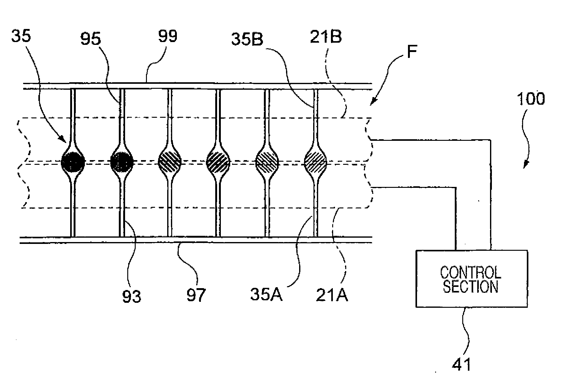
[0068]A first preferred embodiment of an intra-microchannel mixing apparatus according to the invention will be discussed in detail with reference to the accompanying drawings. An intra-microchannel mixing apparatus formed as a part of a sample analysis system will be discussed as one example of the intra-microchannel mixing apparatus.
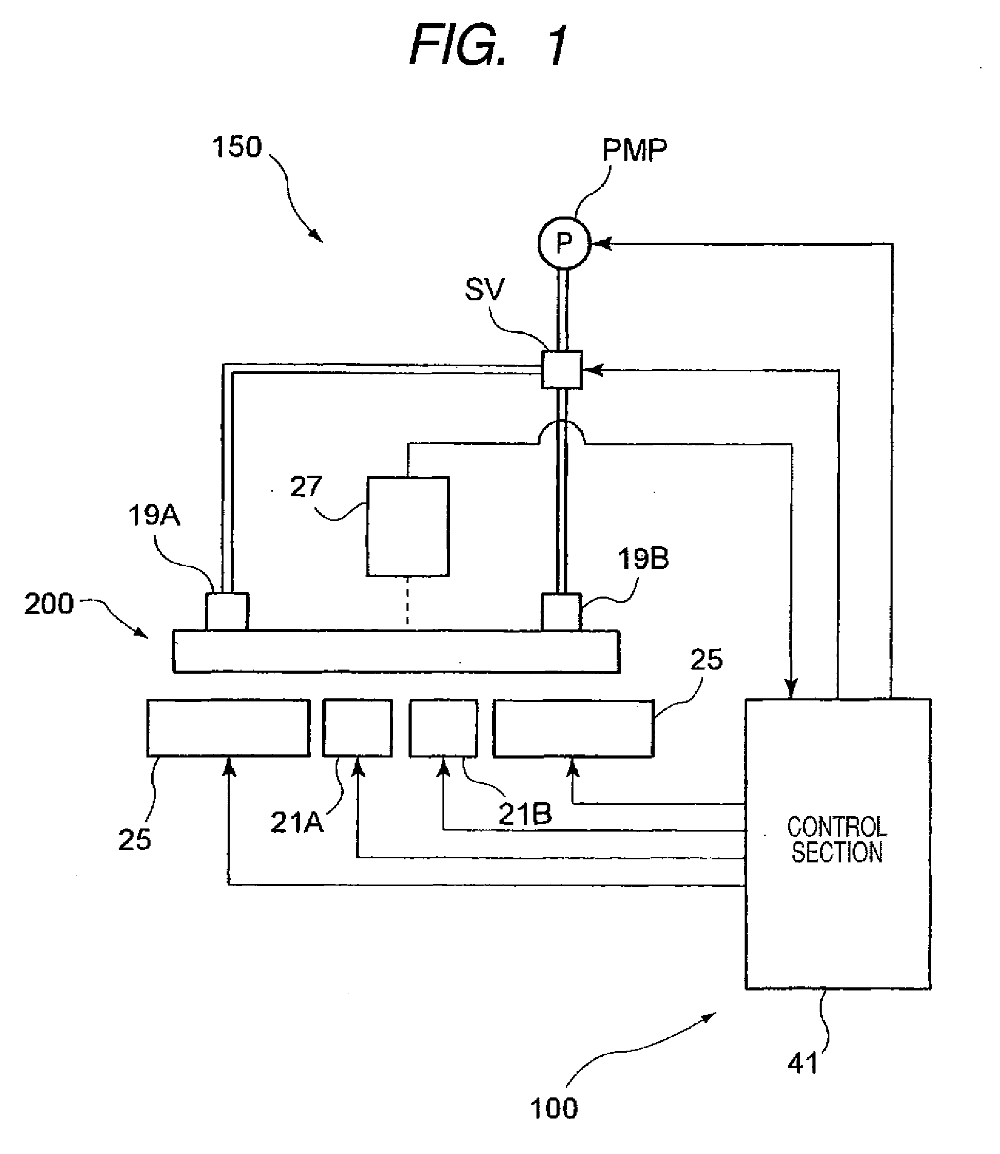
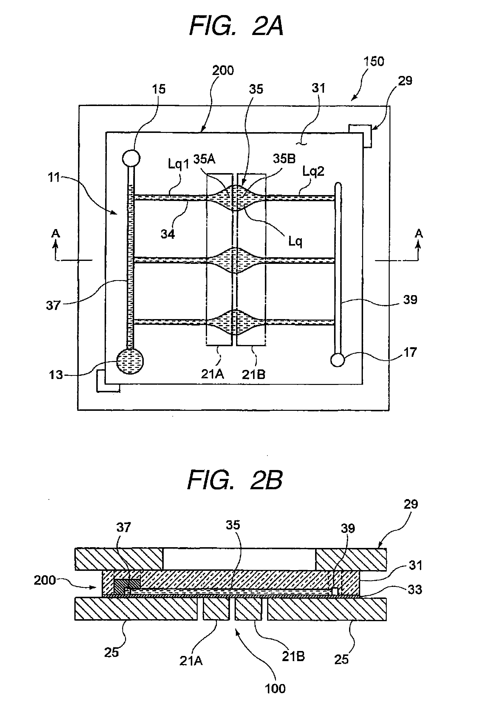
[0069]FIG. 1 is a block diagram of a sample analysis system according to the first preferred embodiment of the invention and FIG. 2A is a plan view of a microfluid chip retention section and FIG. 2B is a sectional view taken on line A-A in FIG. 2A.
[0070]In the embodiment, a microfluid chip 200 (which will also be hereinafter referred to simply as “chip 200”) into which a sample is poured is set in a sample analysis system 150. The microfluid chip 200 is set in the sample analysis system 150, whereby the poured sample liquid is handled by a physical action force from the outside of the chip and, for example, a plurality of target genes of monobasic poly...
second embodiment
[0099]Next, a second embodiment of applying an intra-microchannel mixing apparatus according to the invention to a microfluid chip for analyzing a biosubstance of blood, etc., will be discussed with FIGS. 6 to 10.
[0100]FIG. 6 is a block diagram to represent a microfluid chip of the second embodiment according to the invention together with the schematic configuration of a sample analysis system. FIG. 7 is an exploded perspective view of the microfluid chip shown in FIG. 6. FIGS. 8A and 8B are plan views of the microfluid chip shown in FIG. 7 wherein FIG. 8A is a top view and FIG. 8B is a bottom view. FIG. 9 is an enlarged view of FIG. 8B. FIG. 10 is an enlarged view of a reaction section in FIG. 9. Components identical with or similar to those of the first embodiment are denoted by the same or corresponding reference numerals in the second embodiment and will be briefly discussed or will not be discussed again.
[0101]A microfluid chip 200 of the second embodiment according to the inv...
PUM
 Abstract
Description
Claims
Application Information
 - R&D
- Intellectual Property
- Life Sciences
- Materials
- Tech Scout
- Unparalleled Data Quality
- Higher Quality Content
- 60% Fewer Hallucinations
Browse by: Latest US Patents, China's latest patents, Technical Efficacy Thesaurus, Application Domain, Technology Topic, Popular Technical Reports.
© 2025 PatSnap. All rights reserved.Legal|Privacy policy|Modern Slavery Act Transparency Statement|Sitemap|About US| Contact US: help@patsnap.com


