Discrete element modeling of rock destruction under high pressure conditions

Active Publication Date: 2009-05-21
BAKER HUGHES INC
View PDF0 Cites 24 Cited by
  • Summary
  • Abstract
  • Description
  • Claims
  • Application Information

AI Technical Summary

Benefits of technology

[0010]Rates of penetration based on these models under-predict the effect of downhole pressure on dr

Problems solved by technology

Specifically, the deformation and extrusion of crushed rock detritus c

Method used


Image

  • Discrete element modeling of rock destruction under high pressure conditions
  • Discrete element modeling of rock destruction under high pressure conditions
  • Discrete element modeling of rock destruction under high pressure conditions

Examples


Embodiment Construction

Discrete Element Modeling of Rock Cutting

[0026]Discrete Element Modeling (DEM) materials are created by establishing an equivalence between the mechanical response of selected lab tests and DEM models of the same lab tests. D. O. Potyondy and P. A. Cundall, 2004, A bonded-particle model for rock, Int. J. Rock Mech. Min. Sci. 41(8). pp. 1329-1364. Success in the DEM method requires that appropriate lab tests and mechanical parameters be chosen to calibrate the DEM material. This, of course, presupposes that appropriate lab tests and mechanical parameters may be selected to characterize drilling under pressure. A common practice in the mining industry is to establish an equivalence in: density, elastic modulus, Poisson ratio, Brazilian strength, UCS and N. However, none of these equivalencies describe the inelastic response of the rock.

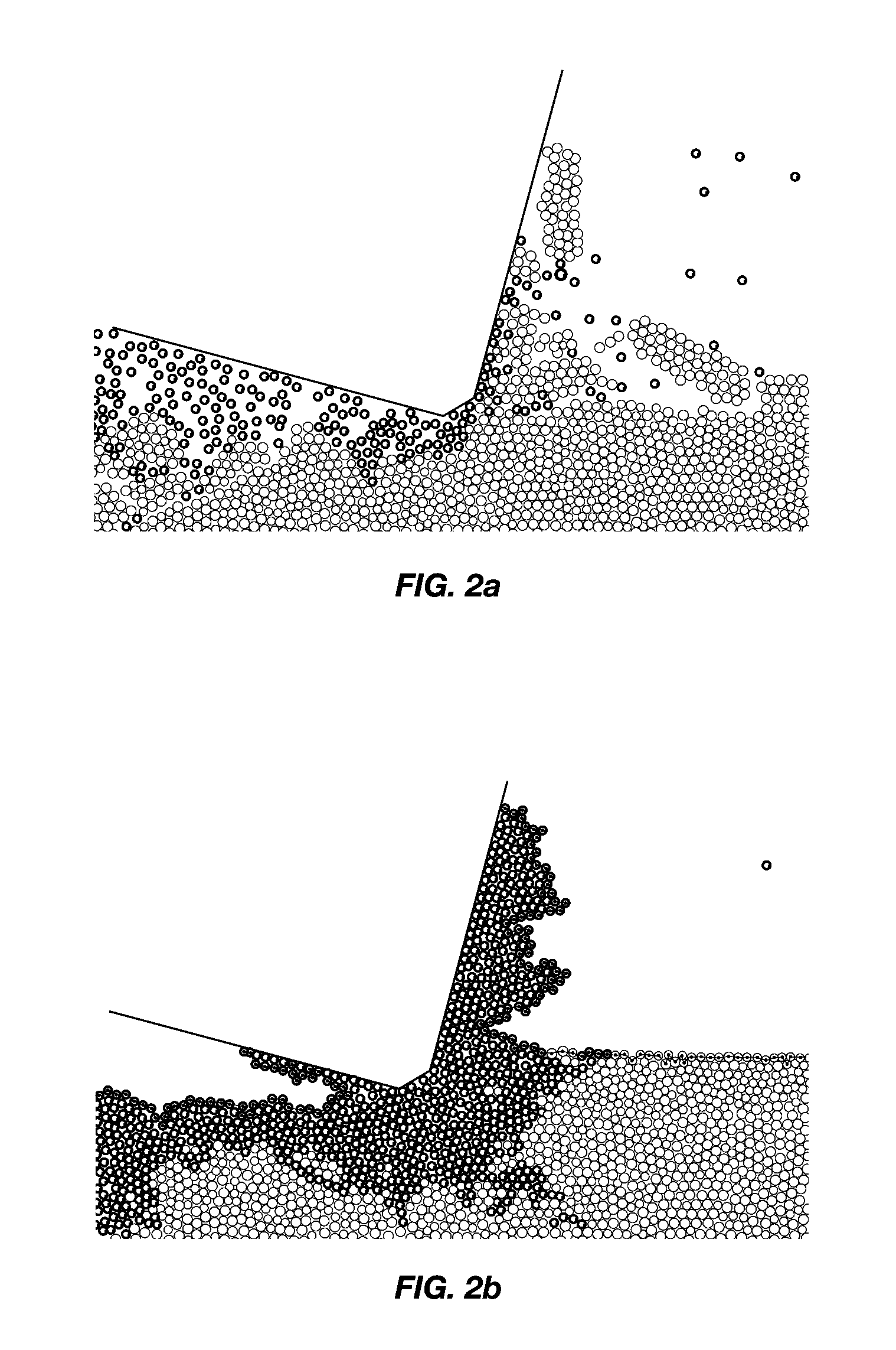
[0027]Rock cutting under pressure is very different from rock cutting at atmospheric conditions. At atmospheric conditions, a cutter drives long cracks...


PUM


Abstract

Discrete Element Modeling (DEM) of rock subject to high confining pressures, such as in a subterranean drilling environment, may be used to predict performance of cutting structures used in drill bits and other drilling tools, as well as of the tools themselves. DEM may also be used to create “virtual” rock exhibiting specific drillability characteristics with or without specific reference to any actual rock, for purposes of assessing cutting efficiency of various cutting structure configurations and orientations, as well as of drilling tools incorporating same.

Description

CROSS-REFERENCE TO RELATED APPLICATIONS[0001]This application claims the benefit of U.S. Provisional Patent Application Ser. No. 60 / 872,057, filed on Nov. 29, 2006 and entitled DISCRETE ELEMENT MODELING OF ROCK CUTTING UNDER HIGH PRESSURE CONDITIONS, the disclosure of which application is hereby incorporated herein in its entirety by this reference.TECHNICAL FIELD[0002]The present invention, in various embodiments, relates to discrete element modeling (DEM) of cutting or otherwise destroying subterranean rock under high pressure conditions, and employing such modeling to improve cutting efficiency of cutters, drill bits and other tools for removing subterranean rock in the context of, by way of nonlimiting example only, drilling or reaming a subterranean borehole.BACKGROUND[0003]During the early part of the twentieth century, the drilling community did not account for the strengthening effect of downhole pressure on rock. I. G. Kühne, 1952, Die Wirkungsweise von Rotarymeiseln and an...

Claims


Application Information

Patent Timeline
IPC IPC(8): G06G7/48
CPCE21B10/00E21B49/00E21B10/55E21B10/08
Inventor LEDGERWOOD, III, LEROY W.
Owner BAKER HUGHES INC
Why Eureka
Try Eureka