
Active combustion control for a turbine engine

a technology of active combustion control and turbine engine, which is applied in the ignition of turbine/propulsion engine, instruments, lighting and heating apparatus, etc., can solve the problems of mechanical damage to turbine components, unstable flame in the combustor, and development of dynamic pressure waves in the combustor, so as to reduce the amount of pilot fuel

Active Publication Date: 2009-05-28
SOLAR TURBINES
View PDF5 Cites 46 Cited by
  • Summary
  • Abstract
  • Description
  • Claims
  • Application Information

AI Technical Summary

Benefits of technology

[0007]In yet another aspect, a method of combustion control of a gas turbine engine is disclosed. The method includes directing a first amount of first fuel into a combustor of the turbine engine, and directing a second amount of second fuel into the combustor circumferentially around the first fuel. A sum of the first amount and the second amount being a total fuel supply to the combustor. The method also includes generating a combustion induced pressure pulse in the combustor, and detecting an amplitude of the pressure pulse that is within a frequency range. The method also includes increasing the first fuel amount to a third amount in response to an amplitude that is above a threshold value. The third amount is greater than about 10% of the total fuel supply. The method further includes decreasing the first fuel amount from the third amount to a fourth amount. The fourth amount is about 0.05% to about 1% greater than the first amount.

Problems solved by technology

While lean fuel-air mixture reduces NOx emissions, reducing fuel content in the mixture below a threshold value may cause the resulting flame in the combustor to be unstable.
Instability of the combustion flame may result in the development of dynamic pressure waves in the combustor.
These pressure pulses can result in mechanical damage to turbine components and smothering of the flame in the combustor (“lean blow-out”).
This approach may, however, exacerbate the problem of controlling NOx production.
Increasing fuel flow through the pilot increases NOx emissions.
Although the combustion control system of the '307 patent may eventually stabilize the combustion process while increasing NOx emission to just the amount needed to achieve stable combustion, the system may have drawbacks.
For instance, the gradual increasing of pilot fuel to achieve stable combustion, as disclosed in the '307 patent, may extend the amount of time the turbine engine operates in an unstable condition, and thus increase the potential for damage to the turbine.

Method used


Image

  • Active combustion control for a turbine engine
  • Active combustion control for a turbine engine
  • Active combustion control for a turbine engine

Examples


Embodiment Construction

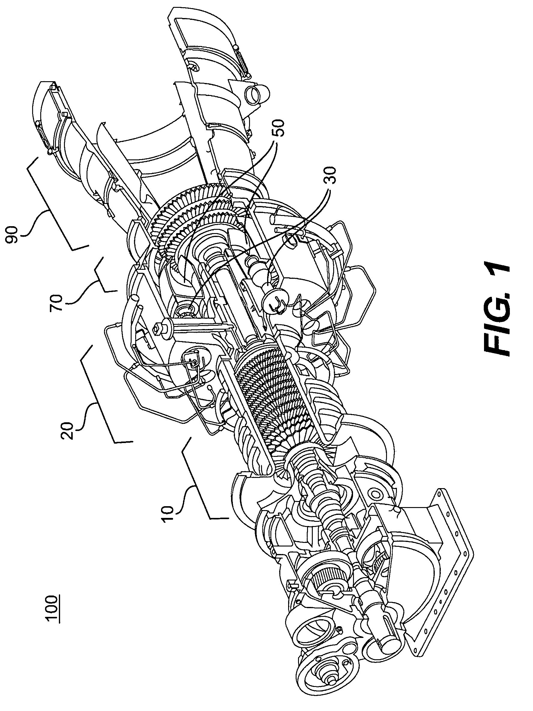
[0012]FIG. 1 illustrates an exemplary gas turbine engine 100. Turbine engine 100 may have, among other systems, a compressor system 10, a combustor system 20, a turbine system 70, and an exhaust system 90. In general, compressor system 10 compresses incoming air to a high pressure, combustor system 20 mixes the compressed air with a fuel and burns the mixture to produces high-pressure, high-velocity gas, and turbine system 70 extracts energy from the high-pressure, high-velocity gas flowing from the combustor system 20. It should be emphasized that, in this discussion, only those aspects of turbine engine 100 useful to illustrate the combustion control process will be discussed.

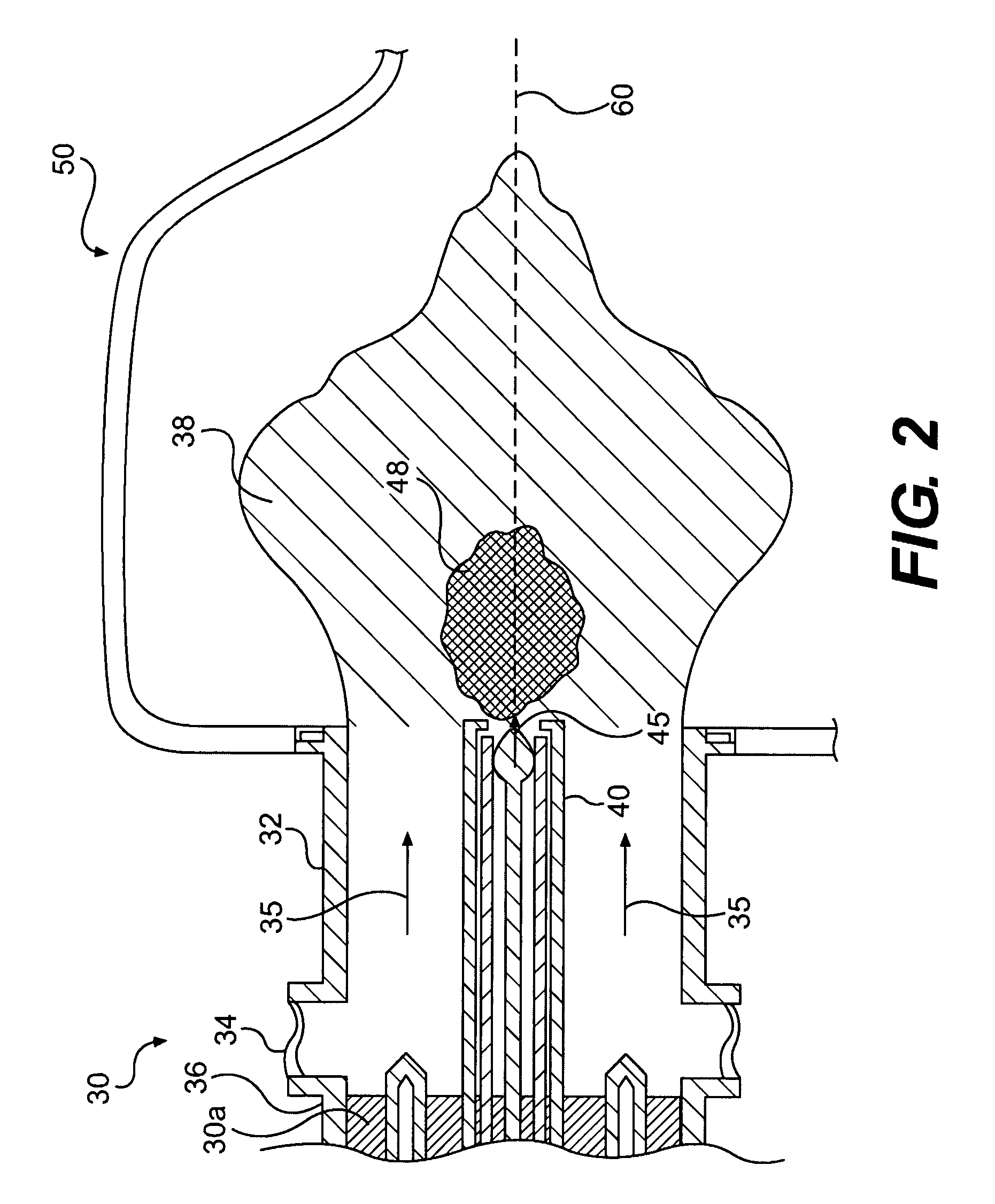
[0013]Compressor system 10 may include any device capable of compressing air. This compressed air may be directed to an inlet port of combustor system 20. Combustor system 20 may include a plurality of fuel injectors 30 configured to mix the compressed air with a fuel and deliver the mixture to one or more co...


PUM


Abstract

A combustion control system for a turbine engine is disclosed. The combustion control system includes a fuel injector having a main fuel supply and pilot fuel supply coupled to a combustor of the turbine engine. The combustion control system also includes a sensor coupled to a transfer tube. The transfer tube is fluidly coupled to the combustor, and the sensor is configured to detect a pressure pulse in the combustor. A semi-infinite coil is also coupled to the transfer tube. The combustion control system also includes a controller electrically connected to the sensor. The controller is configured to compare an amplitude of the pressure pulse within a frequency range to a threshold amplitude, and adjust the pilot fuel supply in response to the comparison.

Description

TECHNICAL FIELD[0001]The present disclosure relates generally to a system and a process for combustion control of a gas turbine engine, and more particularly, to an active combustion control system and process for a turbine engine.BACKGROUND[0002]Gas turbine engines are used for generating power in a variety of applications including land-based electrical power generating plants. Turbine engines produce power by extracting energy from a flow of hot gas produced by combustion of fuel and air in a combustion chamber (“combustor”) of the turbine. These hot gases are directed over rotatable blades to produce mechanical power before being released into the atmosphere. Turbine engines may be designed to combust a broad range of hydrocarbon fuels, such as natural gas, kerosene, diesel, etc in the combustor. Combustion of hydrocarbon fuel results in the production of combustion byproducts, some of which are considered regulated emissions. These regulated emissions include various forms of n...

Claims


Application Information

Patent Timeline
IPC IPC(8): F02C9/26
CPCF23N5/00F23N2025/04F23R2900/00013F23R3/286F23R3/343F23N2041/20F23N2225/04F23N2241/20
Inventor MENDOZA, ROBERT ELEAZARMORRISON, PAUL ELLIOTLEON, MARCO EZRABOGNUDA, TIZIANO MARCOITO, SATOSHI
Owner SOLAR TURBINES
Learn More