Selective NOx catalytic reduction system including an ammonia sensor

a catalytic reduction and sensor technology, applied in the direction of engines, mechanical equipment, machines/engines, etc., can solve the problems of excessive ammonia in the tailpipe, difficult to achieve, and untreated engine exhaust typically contains an unacceptable level of nox, so as to reduce the size, volume, complexity and cost of the scr system, and reduce the hysteresis. , the effect of speeding up the respons

Inactive Publication Date: 2009-05-28
DELPHI TECH INC
View PDF10 Cites 35 Cited by
  • Summary
  • Abstract
  • Description
  • Claims
  • Application Information

AI Technical Summary

Benefits of technology

[0016]Briefly described, an improved SCR system in accordance with the invention comprises a least one ammonia sensor disposed at an intermediate longitudinal location in an NOx-reducing SCR catalyst and in communication with an Engine Control Module (ECM). Locating the ammonia sensor within the catalyst allows for optimal NOx reduction and permits the downstream NOx catalyst to be treated as an effective slip catalyst, thus minimizing or eliminating the need for a second slip catalyst and housing, and reducing the size, vol

Problems solved by technology

Even under the best of control, however, untreated engine exhaust typically contains an unacceptable level of NOx.
In practice, this has proved to be very difficult to achieve.
First, excess ammonia in the tailpipe exhaust can be due to incomplete reaction of the SCR as shown in Eqs. 1-3.
Second, in the SCR catalytic reaction mechanism, NOx reacts with ammonia stored on the catalyst. Ammonia storage capacity is highly dependent on temperature of the catalyst, with capacity at low temperatures being significantly greater than at higher temperatures. Because of this effect, even when dosing is greatly reduced or even stopped completely during hot exhaust transients, unreacted ammonia can be desorbed from the SCR catalyst and pass into the tail

Method used


Image

  • Selective NOx catalytic reduction system including an ammonia sensor
  • Selective NOx catalytic reduction system including an ammonia sensor
  • Selective NOx catalytic reduction system including an ammonia sensor

Examples


Embodiment Construction

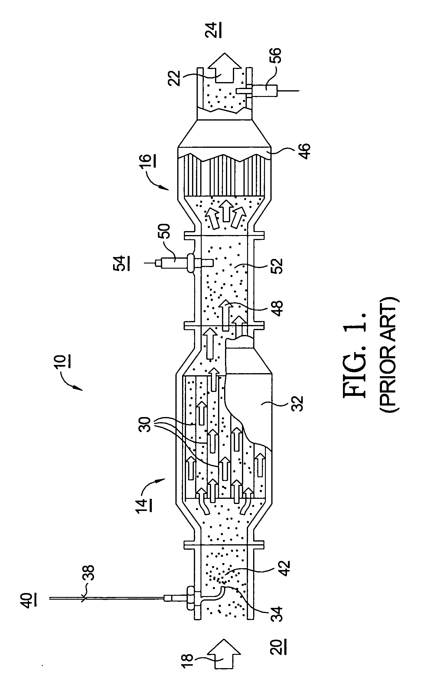
[0023]The benefits and advantages of the present invention may be better appreciated by first considering a prior art SCR system.

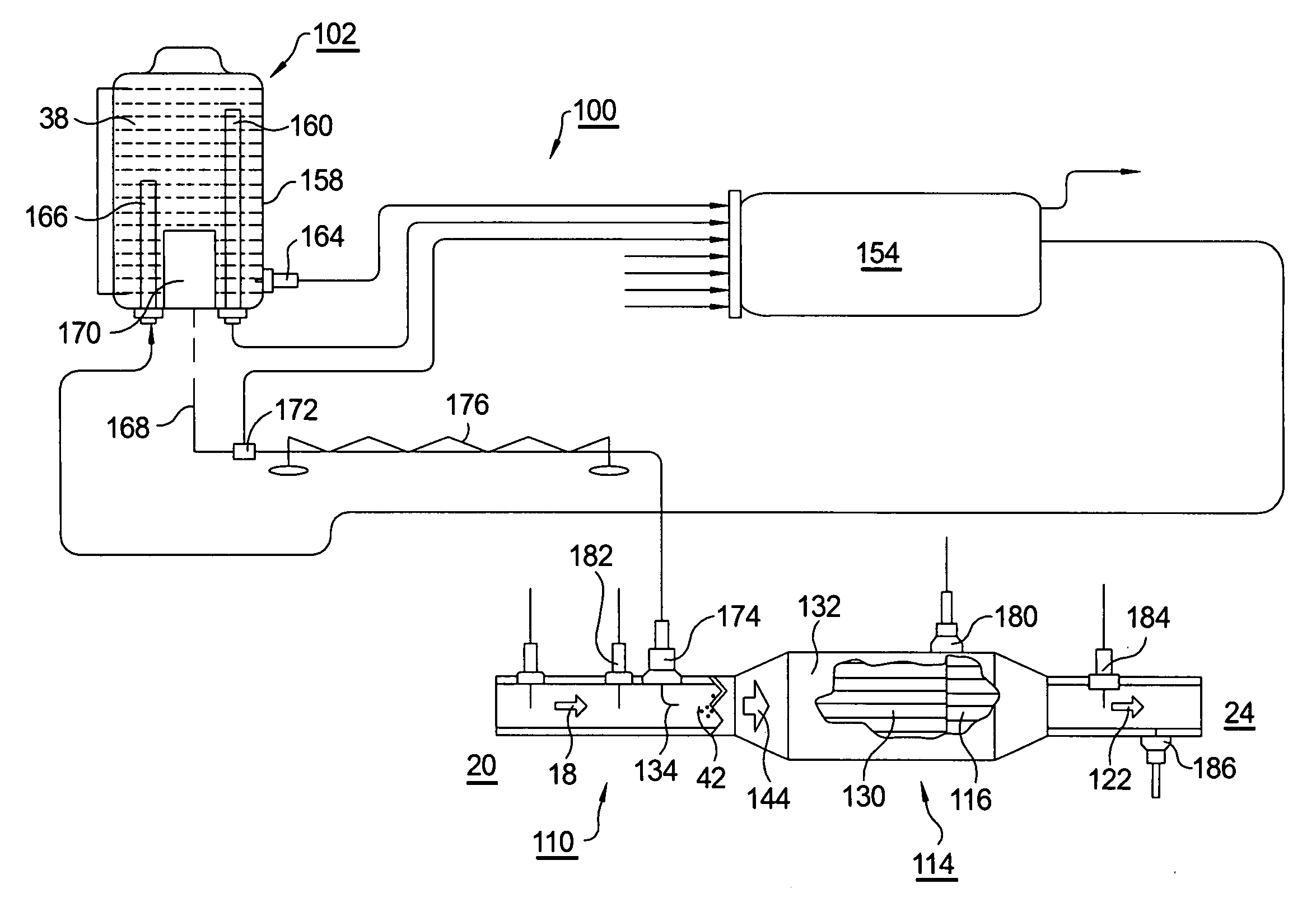
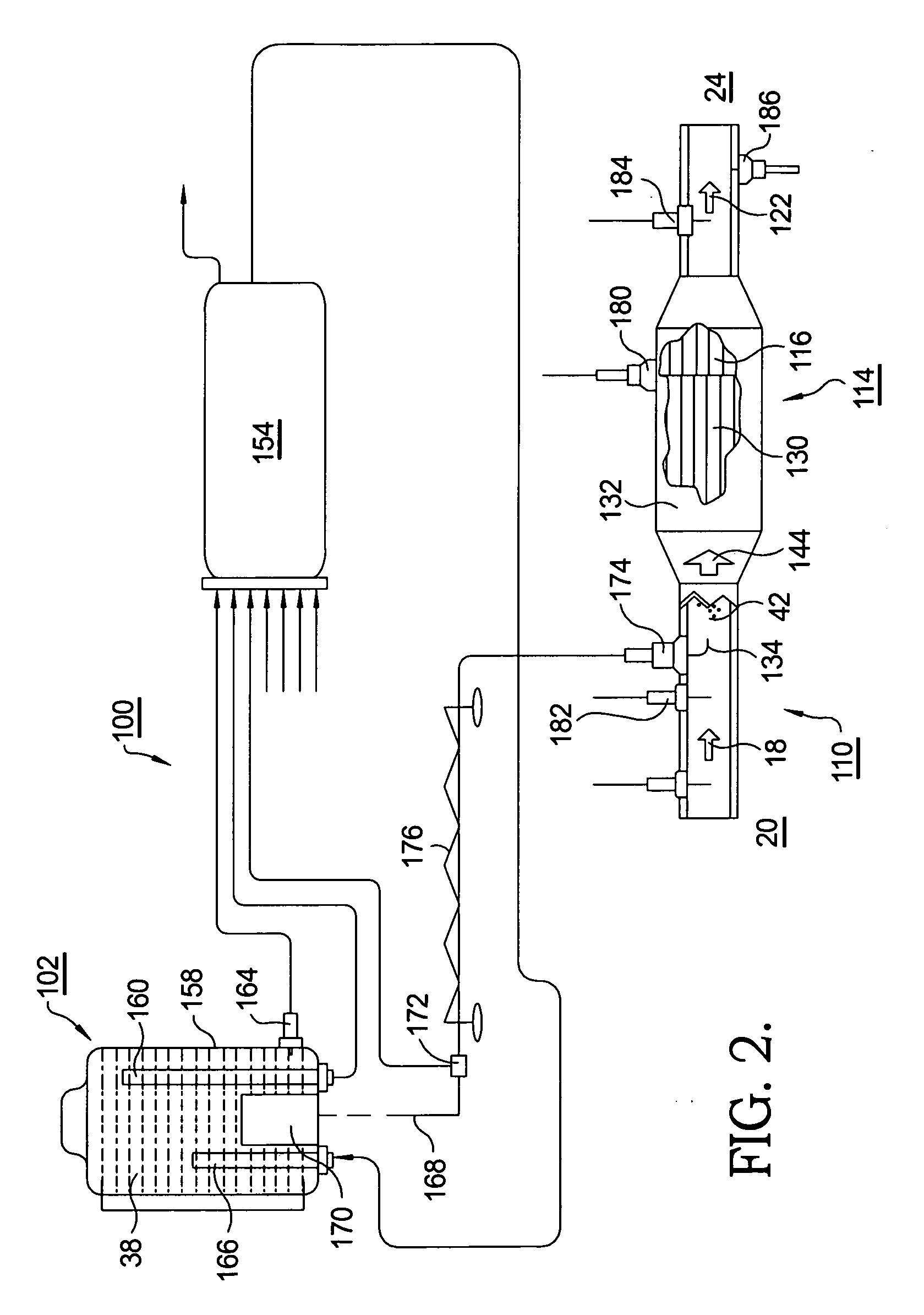
[0024]Referring to FIG. 1, a catalyst assembly 10 in a prior art SCR system comprises a Selective Catalytic Reduction (SCR) unit 14 and an optional ammonia slip catalyst 16 connected in sequence to treat raw engine exhaust 18 from an internal combustion engine 20, especially a diesel or gas engine operated with excess oxygen in the exhausted gases, and to discharge treated engine exhaust 22 to atmosphere 24.

[0025]SCR 14 includes a first selective catalyst 30 disposed in a first housing 32 for selectively reducing NOx to N2 in the presence of NH3 and O2, as described above, in known fashion. An atomizing nozzle 34 prior to SCR 14 receives a reductant solution 38 containing urea and / or ammonia from a source 40 and sprays atomized reductant solution 42 into exhaust 18.

[0026]Slip catalyst 16, a second selective catalyst, is disposed in a second housing 46 for ...


PUM


Abstract

An improved SCR system for controlling NOx levels in internal combustion engine exhaust, comprising a least one ammonia sensor disposed at an intermediate longitudinal location in an SCR catalyst and in communication with a System Control Module (SCM). The ammonia measurement permits calculation of ammonia storage on catalyst sites via a stored SCM algorithm. Locating the ammonia sensor midway in the catalyst allows for optimum control of NOx reduction and permits the portion of the catalyst downstream of the sensor to be treated as a slip catalyst, thus minimizing or eliminating the need for a second slip catalyst and housing, and reducing the size, volume, complexity, and cost of an SCR system. In-brick ammonia sensor permits the system to manage engine exhaust to a desired NOx conversion level and ammonia slip target value, thus minimizing the rate of consumption of ammonia while meeting required limits for NOx emissions.

Description

TECHNICAL FIELD[0001]The present invention relates to systems for controlling the level of nitrogen oxides (NOx) in internal combustion engine exhaust; more particularly, to such systems for catalytically reducing NOx to N2 by reaction with ammonia; and most particularly, to an improved system having an ammonia sensor disposed within the catalyst for feedback control to manage exhaust levels of NOx and ammonia.BACKGROUND OF THE INVENTION[0002]Reducing and controlling engine emissions of oxides of nitrogen are important considerations in modern internal combustion engines, both spark-ignited and compression-ignited. NOx emissions are an element of smog production, and emissions limits mandated by state governments and / or the federal government are likely to become even more stringent in the future.[0003]One known approach to reducing NOx emissions is to reduce NOx formation by reducing combustion temperatures, such as by recirculation of exhaust gas into the engine firing chambers to...

Claims


Application Information

Patent Timeline
IPC IPC(8): F01N3/20
CPCF01N3/2066F01N2560/021F01N13/0093Y02T10/24F01N13/0097F01N2610/02Y02T10/12
Inventor SHOST, MARK A.
Owner DELPHI TECH INC
Why Eureka
Try Eureka