Balanced amplifier and electronic circuit

a balanced amplifier and electronic circuit technology, applied in differential amplifiers, amplifiers with semiconductor devices/discharge tubes, amplifiers, etc., can solve the problems of unbalanced reverse-phase signals, generated by two operational amplifiers, and small delay in time (or phase shift) between

Inactive Publication Date: 2009-05-28
PIONEER CORP
View PDF7 Cites 7 Cited by
  • Summary
  • Abstract
  • Description
  • Claims
  • Application Information

AI Technical Summary

Benefits of technology

[0014]As described above, according to the balanced amplifier of the present invention, although it generates the positive-phase signal and the reverse-phase signal to each of which the reference voltage, which is e.g. a direct current signal, is superimposed, it has the same number of operational amplifiers used for the generation of the positive-phase signal and for the generation of the reverse-phase signal. Thus, there is little or no chance of the delay in time (or phase shift) between the positive-phase signal and the reverse-phase signal. In addition, it is possible to almost match the noise characteristic and the distortion characteristic or the like in each of the positive-phase signal and the reverse-phase signal. By this, it is possible to preferably generate the balanced signal (i.e. each of the positive-phase signal and the reverse-phase signal) in relatively good quality to which the direct current signal is superimposed.
[0015]In addition, it is unnecessary to use a capacitor for preventing the reference voltage from returning (feedback). Thus, it is possible to preferably prevent the deterioration of the signal characteristic of the balanced signal caused by the material of the electrode foil of the capacitor or the material of the dielectric substance of the capacitor. As a result, it is possible to preferably prevent the deterioration of the sound quality of music outputted from audio equipment using the balanced amplifier of the present invention. Moreover, without limiting the technical effect on the audio equipment, the balanced amplifier can perform an operation in a direct current zone.
[0023]By this, as described above, it is possible to preferably generate the balanced signal (i.e. each of the positive-phase signal and the reverse-phase signal) in relatively good quality to which the direct current signal is superimposed.

Problems solved by technology

That is, in order to generate the reverse-phase signal, it is necessary to use an extra operational amplifier, compared to a construction which generates the positive-phase signal, so that there is such a technical problem that a slight delay in time (or phase shift) occurs between the generated positive-phase signal and reverse-phase signal.
Moreover, a noise characteristic and a distortion characteristic or the like are also caused by each of the operational amplifiers, so that there is also such a technical problem that the noise characteristic and the distortion characteristic in each of the positive-phase signal, generated by one operational amplifier, and the reverse-phase signal, generated by two operational amplifiers, are unbalanced.
In addition, the capacitor is used to prevent the direct current voltage from returning (feedback); however, in the audio equipment or the like, there is such a technical problem that the material of the electrode foil of the capacitor or the material of a dielectric substance of the capacitor may deteriorate the outputted signal characteristics and may deteriorate sound quality.

Method used


Image

  • Balanced amplifier and electronic circuit
  • Balanced amplifier and electronic circuit
  • Balanced amplifier and electronic circuit

Examples


Embodiment Construction

[0045]Hereinafter, the best mode for carrying out the present invention will be explained with reference to the drawings.

[0046]Hereinafter, an embodiment of the present invention will be explained with reference to the drawings.

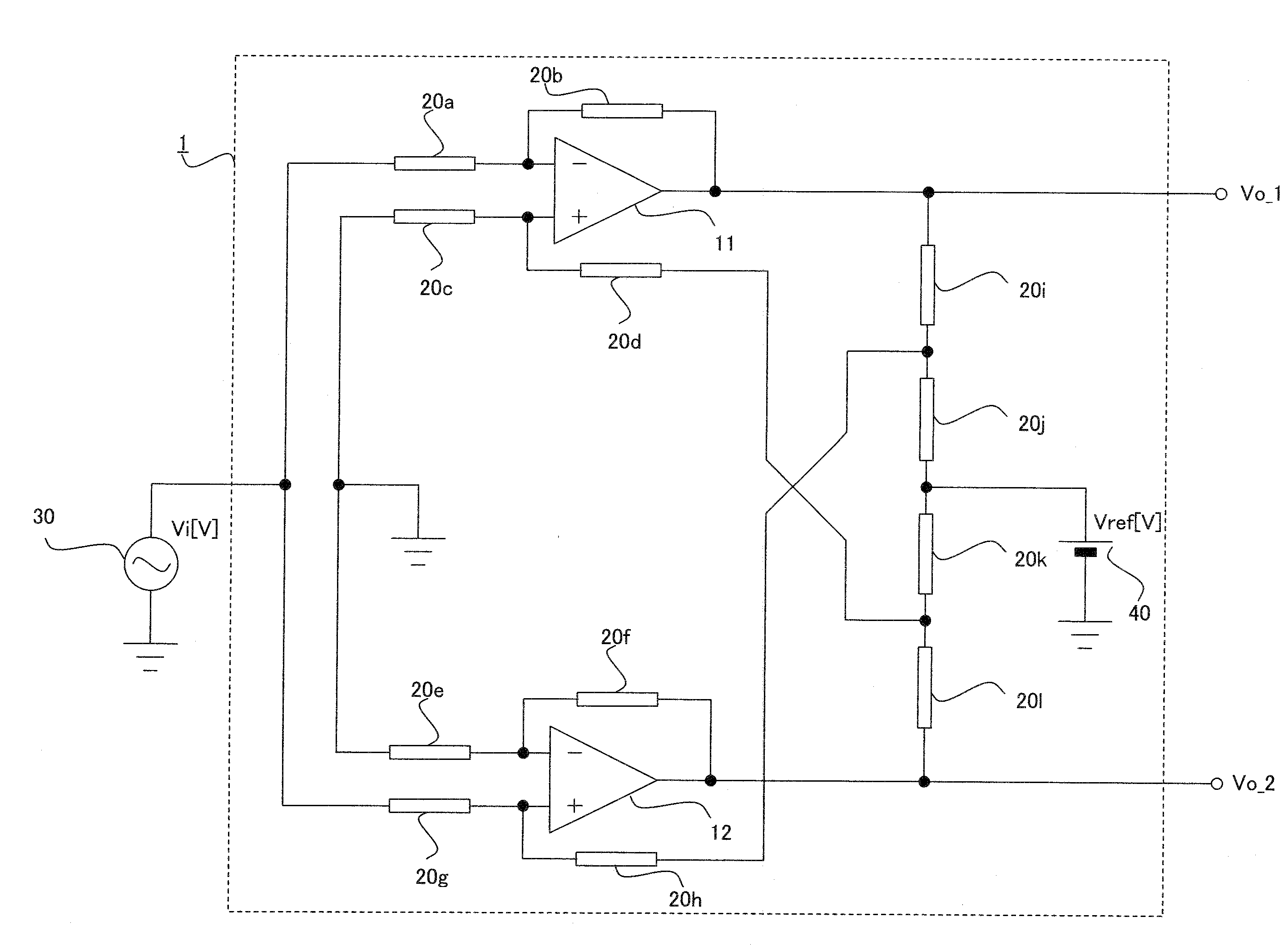
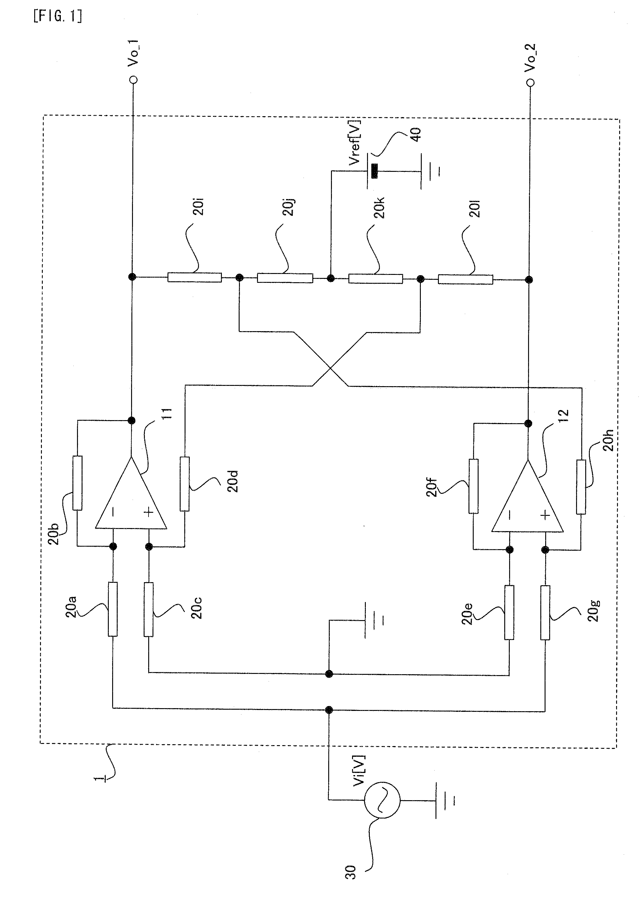
[0047]Firstly, with reference to FIG. 1, a balanced amplifier in the embodiment of the present invention will be explained. FIG. 1 is a circuit diagram conceptually showing the circuit structure of the balanced amplifier in the embodiment.

[0048]As shown in FIG. 1, a balanced amplifier 1 is provided with: an operational amplifier 11, which constitutes one specific example of the “first operational amplifier” of the present invention; an operational amplifier 12, which constitutes one specific example of the “second operational amplifier 12” of the present invention; a resistance 20a; a resistance 20b; a resistance 20c; a resistance 20d, which constitutes one specific example of the “sixth resistance” of the present invention; a resistance 20e; a resistance 20f...


PUM


Abstract

A balanced amplifier (1) is provided with: a first operational amplifier (11) whose reverse-phase input terminal is connected to an input voltage source (30) and whose reverse-phase input terminal is connected to an output terminal of the first operational amplifier; a second operational amplifier (12) whose positive-phase input terminal is connected to the input voltage source and whose reverse-phase input terminal is connected to an output terminal of the second operational amplifier; and a voltage division circuit (20i, 20j, 20k, 20l) for dividing a reference voltage supplied from a reference voltage source (40), the reference voltage source being connected to a positive-phase input terminal of each of the first operational amplifier and the operational amplifier through the voltage division circuit.

Description

TECHNICAL FIELD[0001]The present invention relates to a balanced amplifier for outputting a balanced signal, used inside audio equipment, and an electronic circuit provided with the balanced amplifier.BACKGROUND ART[0002]For example, in the audio equipment, such as an amplifier, in order to realize a good S / N ratio when a digital signal is generated from an analog signal, a differential AD converter driving circuit is used. In the differential AD converter driving circuit, instead of generating the digital signal directly is from the single analog signal, each (i.e. balanced signal) of a positive-phase signal, which is in phase with the analog signal, and a reverse-phase signal, which is out of phase to the analog signal by 180 degrees, is generated (i.e. balanced signal is generated), and then the digital signal is generated from each of the positive-phase signal and the reverse-phase signal. At this time, the general differential AD converter driving circuit uses a source voltage ...

Claims


Application Information

Patent Timeline
Patent Type & Authority Applications(United States)
IPC IPC(8): H03F1/26
CPCH03F1/34H03F2203/45138H03F3/45475
Inventor NISHIZAWA, TATSUYA
Owner PIONEER CORP
Why Eureka
Try Eureka