

In-transitcar alarm
a technology for car theft and alarm, which is applied in the direction of anti-theft devices, program control, instruments, etc., can solve the problems of car theft, tracking down and identifying, and parts cannot be identified as easily as the original auto,
- Summary
- Abstract
- Description
- Claims
- Application Information
AI Technical Summary
Benefits of technology
Problems solved by technology
Method used
Image

Examples
first embodiment
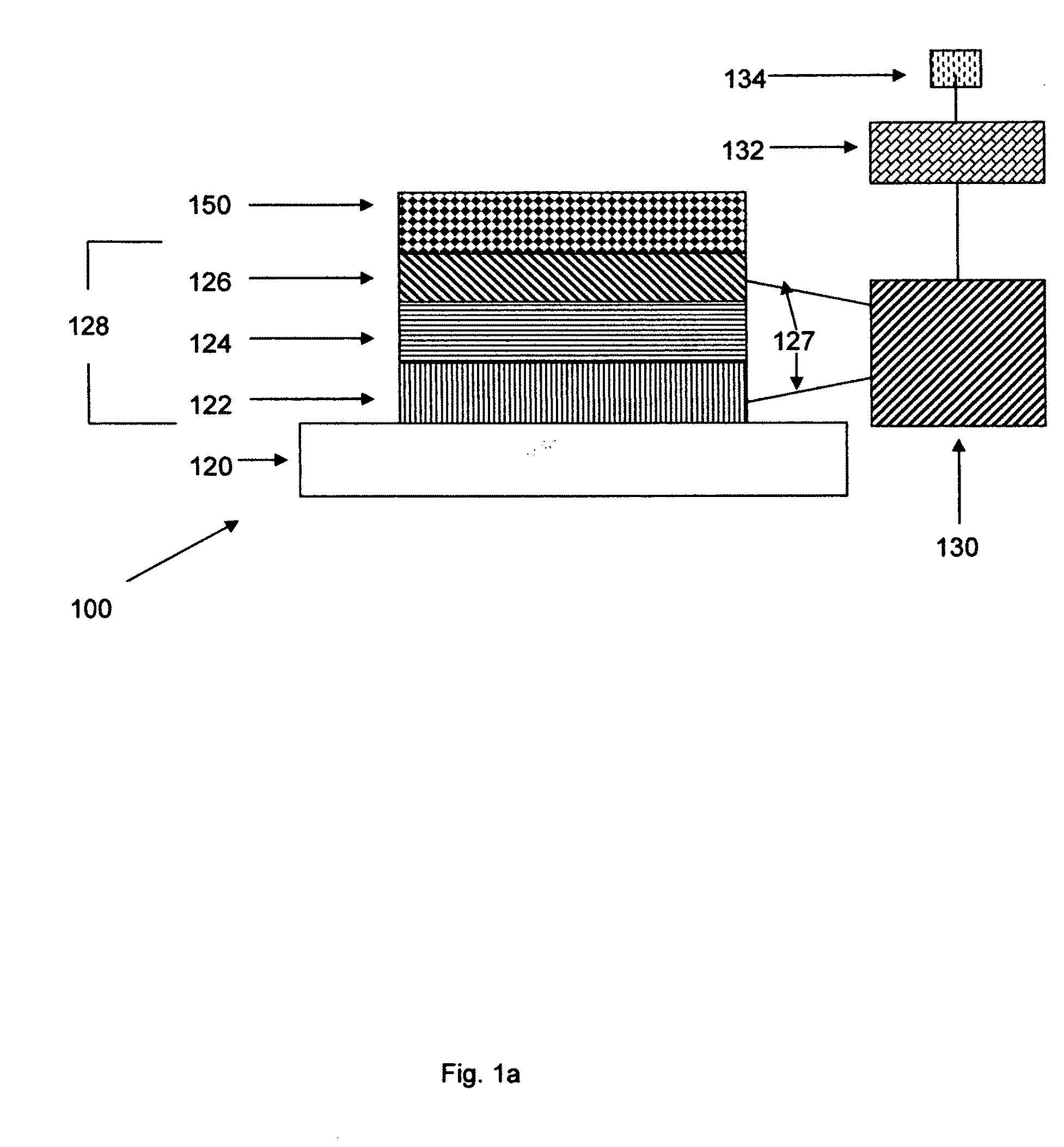
[0056]Reference is now made to FIG. 1a, which is a schematic view of a car anti-theft system (100) that is constructed and operative in accordance with a preferred embodiment of the present invention. In FIG. 1a is shown a side view of an OLED patterned onto a car window. Specifically, car window (120) serves as transparent substrate for a conductive anode (122) layer of indium tin oxide (ITO). Indium tin oxide is optically-transparent and serves to inject holes into an organic light emitting material (124) that sits directly above the ITO conductive anode (122). Above the organic light emitting material (124) layer is a gold conductive cathode (126) that injects electrons into the organic light emitting material (124). Note that conductive cathode (122) and conductive anode (126) are attached through wires (127) to a battery (130). Car window (120), conductive cathode (122), organic light-emitting material (124) and conductive anode (126) together form an OLED (128) according to th...
example 1
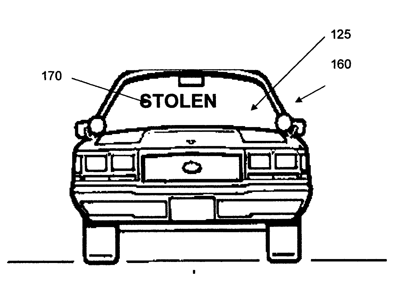
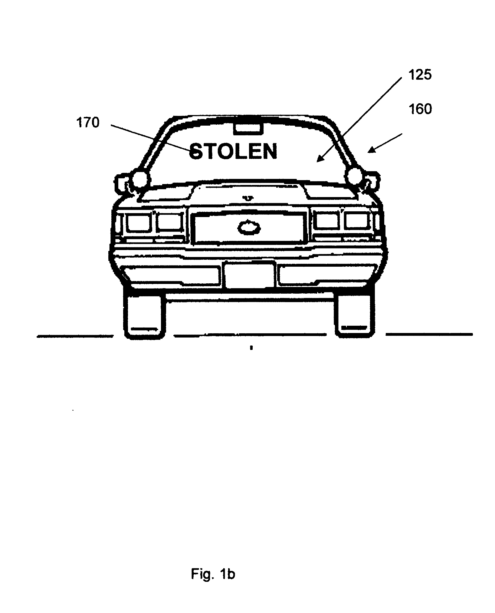
[0067]Reference is made to FIG. 2a. In the figure is a car (260) with a window-associated patterned OLED (270) in the form of the word expression “CALL 911”. This word expression is invisible under normal conditions and is shown in light grey for ease of understanding of the present invention only. “CALL 911” is patterned from multiple separate OLED's on front car windshield (225). In FIG. 2b, during car theft, said OLED's are powered by a battery (not shown in this figure), and the word expression “CALL 911” on the front car windshield (225) is eminently visible to anyone close to the car (260). This state of affairs allows for contact of police for the purpose of capturing the thief / thieves and return of the car (260). Additionally, activation of the window-associated patterned OLED (270) due to car theft causes additional alarm systems (sound-based—not shown; GPS-based—not shown) to function.
example 2
[0068]One does not explicitly need an organic light-emitter for the present invention, though organic LED's have clear advantages with respect to ease of coating curved glass surfaces. Any material that can give off light in response to an applied voltage when said material and its associated electrodes are patterned onto a car window or an external car surface may be used as the lighting component in the present car anti-theft invention. Reference is now made to FIG. 3a, which is a schematic view of a car anti-theft system (300) that is constructed and operative in accordance with an embodiment of the invention. Specifically, the car anti-theft system (300) includes an external car surface (321) onto which is patterned an inorganic light-emitter (323) attached with two wires (327) to a battery (330). The battery is in turn connected to a retina scanner (333) that is in turn connected to a motion-detector element (335). If the retina scanner (333) does not recognize the person sitti...
PUM
 Abstract
Description
Claims
Application Information