
Liquid crystal display

a liquid crystal display and display technology, applied in non-linear optics, instruments, optics, etc., can solve the problems of reducing the contrast of lcd, using violet pigments, deteriorating heat resistance and chemical resistance, etc., and achieve the effect of improving color saturation and saturation of monochromatic primaries

Inactive Publication Date: 2009-05-28
AU OPTRONICS CORP
View PDF5 Cites 8 Cited by
  • Summary
  • Abstract
  • Description
  • Claims
  • Application Information

AI Technical Summary

Benefits of technology

[0009]In light of the foregoing, the present invention is directed to an LCD simultaneously improving color saturation and saturation of monochromatic primaries, e.g. blue saturation and green saturation.
[0014]In light of the foregoing, through controlling the distribution of the relative maximum brightness peak intensity in the emission spectrum of the backlight module and through adjusting the emission spectrum of the corresponding color filter layer, the blue saturation and the green saturation achieved by the LCD of the present invention can be boosted.

Problems solved by technology

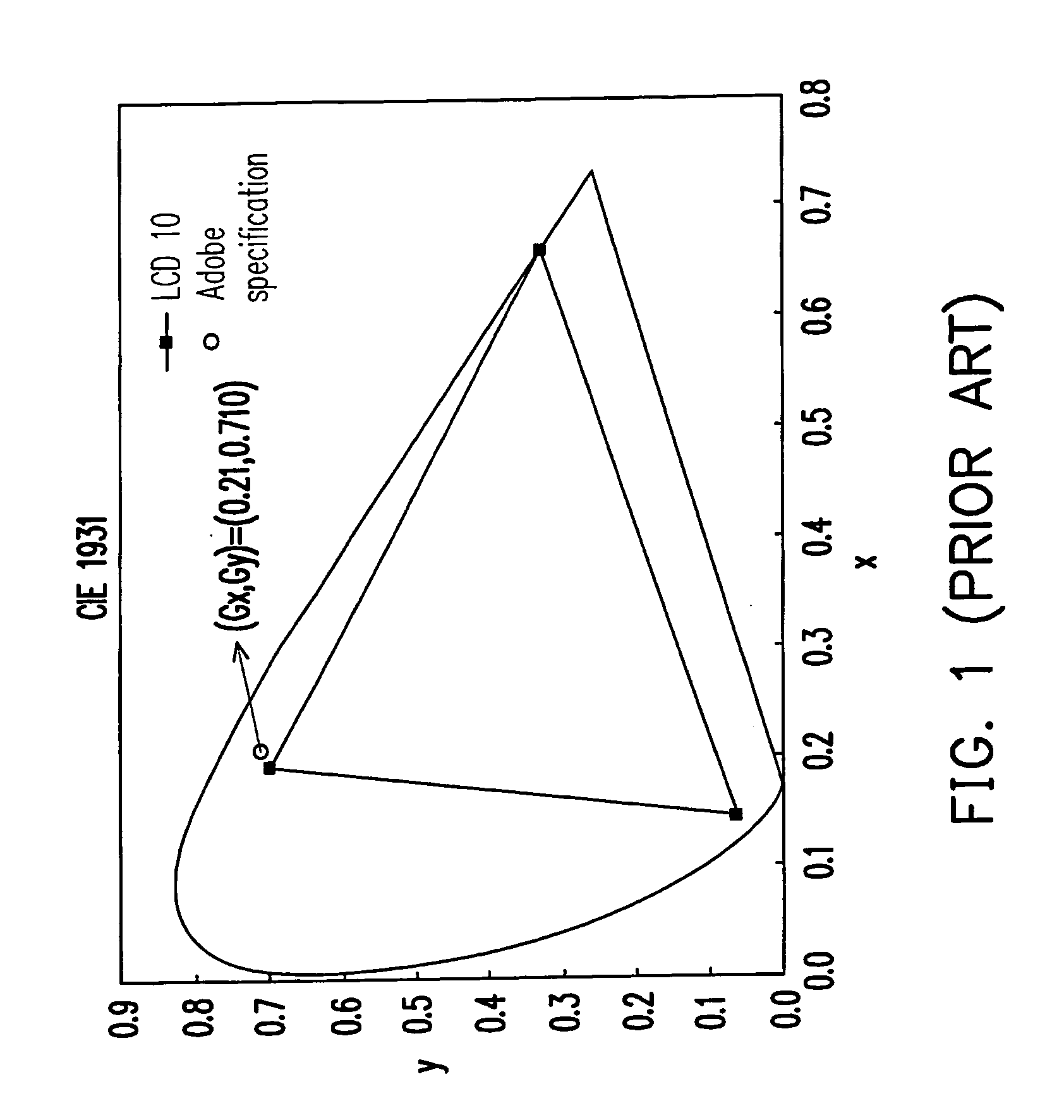
Nevertheless, some drawbacks have been brought up when the LCD 10 aims at improving blue saturation and green saturation.
However, adding excessive violet pigments often gives rise to a reduced contrast of the LCD.
Moreover, the use of the violet pigments, in most cases, deteriorates heat resistance and chemical resistance.
In other words, green saturation of the LCD 10 is barely satisfactory.

Method used


Image

  • Liquid crystal display
  • Liquid crystal display
  • Liquid crystal display

Examples


Embodiment Construction

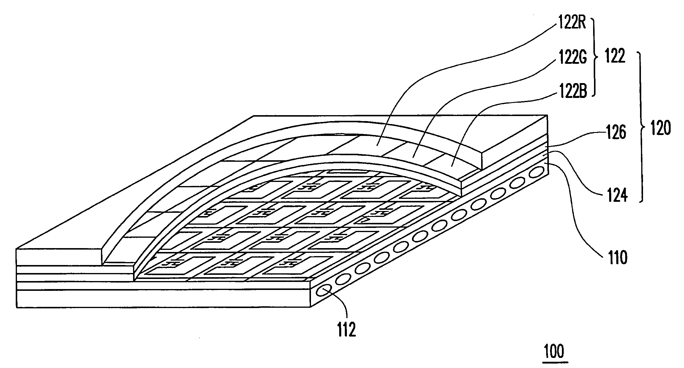
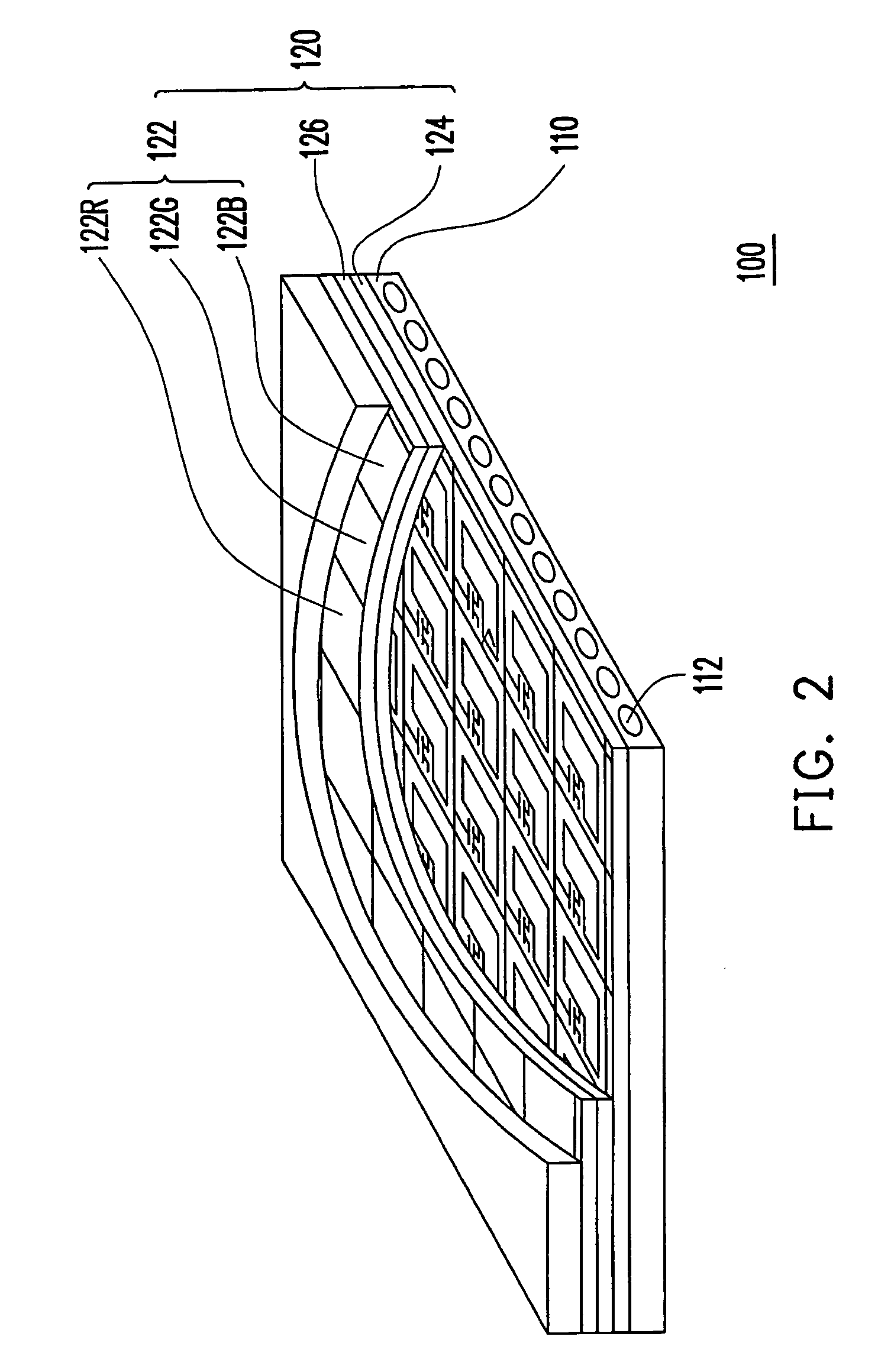
[0020]FIG. 2 is a schematic view illustrating an LCD according to the present invention. Referring to FIG. 2, an LCD 100 includes a backlight module 110 and an LCD panel 120. The backlight module 110 is, for example, a direct type backlight module or an edge-light type backlight module. Further, the backlight module 110 has at least one white light source 112. In the present embodiment, a CCFL is utilized for exemplifying the white light source 112.

[0021]Specifically, an inner wall of the white light source 112 is equipped with a plurality of phosphor materials including red phosphor, green phosphor, and blue phosphor, for example, so as to modulate optical characteristics of the white light source 112, such as luminance, chromaticity, and so on. In addition, color saturation of the phosphors is a key factor determining the entire chromaticity performance. Here, the white light source 112 in the LCD 100 employs Sr5(PO4)3CL:Eu as the blue phosphor, such that an emission spectrum of t...


PUM


Abstract

A liquid crystal display (LCD) including a backlight module and a LCD panel is provided. The backlight module has at least one white light source. BL1 and BL2 respectively represent a relative maximum brightness peak of an emission spectrum of the backlight module at a wavelength from 445 nm to 448 nm and from 510 nm to 520 nm. The LCD panel including two substrates and a liquid crystal layer sandwiched between the two substrates is disposed above the backlight module. One of the two substrates has a red filter layer, a green filter and a blue filter layer. Specially, Gx represents an x coordinate in a CIE 1931 chromaticity diagram when the green filter layer uses a CIE standard light source C, and Gx is larger than or equal to 0.286 (Gx≧20.286).

Description

CROSS-REFERENCE TO RELATED APPLICATION[0001]This application claims the priority benefit of Taiwan application serial no. 96145183, filed on Nov. 28, 2007. The entirety the above-mentioned patent application is hereby incorporated by reference herein and made a part of specification.BACKGROUND OF THE INVENTION[0002]1. Field of the Invention[0003]The present invention generally relates to a display, and more particularly, to a liquid crystal display (LCD).[0004]2. Description of Related Art[0005]LCDs featuring favorable display quality, great space utilization, low power consumption and non-radiation have become prevailing displays little by little. One of the determinative factors of purchasing the widespread LCDs is color reproduction, and thus various techniques to achieve high color reproduction have been proposed for satisfying consumers' demands.[0006]The LCD mainly includes an LCD panel and a backlight module providing a light source to the LCD panel. The LCD panel includes, f...

Claims


Application Information

Patent Timeline
IPC IPC(8): G02F1/13357
CPCG02F1/1336G02F1/133514
Inventor WANG, CHUN-CHIEHLIAO, CHEN-HSIEN
Owner AU OPTRONICS CORP
Learn More