Optical fiber mode coupling device, having an optimized fiber interface and method of fabrication thereof

a fiber interface and optical fiber technology, applied in the field of optical fiber mode coupling devices, can solve the problems of occupying valuable space in digital communication system components, edcs are relatively bulky, and the approach suffered from a number, so as to facilitate the connection to a conventional optical fiber, maximize the coupling, and achieve the effect of high degree of ruggedness and reliability

Active Publication Date: 2009-05-28
CHIRAL PHOTONICS
View PDF1 Cites 18 Cited by
  • Summary
  • Abstract
  • Description
  • Claims
  • Application Information

AI Technical Summary

Benefits of technology

[0017]The present invention is directed to a novel optical fiber mode coupling device, capable of being readily connected to a conventional optical fiber with a high degree of ruggedness and reliability. The inventive mode coupling device only allows transmission of at least one supported fiber mode therethrough, and is preferably configured to maximize the coupling, of at least one desired fiber mode, to the at least one supported fiber mode.
[0018]Advantageously, the inventive mode coupling device is capable of performing the functions of a mode filter for the signal entering its first end, or serving as a mode conditioner for the signal entering its opposite second end. Thus, in one practical application thereof, the novel mode coupling device functions as a mode filter by maximizing the coupling between at least one desired fiber mode of a multi-mode input signal entering the device's first end, and at least one supported mode of the device, to produce an output signal at the device's second end that comprises at least one predetermined fiber mode, corresponding to at least one desired fiber mode.
[0019]In another practical application thereof, the novel mode coupling device functions as a mode conditioner by maximizing the coupling between an input signal, comprising at least one predetermined fiber mode, that enters the device's second end, and, and at least one supported mode of the device, to produce an output signal at the device's first end that comprises at least one desired fiber mode, corresponding to a conditioned at least one predetermined fiber mode.

Problems solved by technology

This approach suffered from a number of drawbacks.
First the EDCs are relatively bulky and thus take up valuable space in digital communication system components.
Second, such devices require electrical power and fail if the power ceases to be supplied.
Third, EDC are relatively expensive.
However, the '857 application mode filter 2, is flawed in several ways.
First, the proposed taper-down (taper 8) and then, without interruption taper-up (taper 6) configuration, will not result in sufficient rejection of modes other than the single mode desired within the multimode fiber connected to taper 8.
Furthermore, the refractive index contrast between the fiber cladding and the surrounding medium at the taper 8-taper 6 interface, will result in a correspondingly higher number of undesired fiber modes, in addition to the fundamental mode, that would be entering the taper 4, thereby significantly disrupting the operation of the '857 application mode filter 2.
Such a significant difference between the diameter of the taper at its connecting end, and the optical fiber to which it must be connected, greatly reduces the rigidity and ruggedness of the connection, and thus significantly decreases the mode filter device reliability.
Moreover, this arrangement significantly increases the difficulty of centering the mode filter device and the SMF 16′ along the same central longitudinal axis.
The '857 application mode filter does not have any effect on polarized fiber modes (as it lacks any structure for isolating and / or filtering polarized modes, and further lacks any teaching or suggestion for doing so).
As a result, even if the mode filter of the '857 application were capable of performing its recited functions, it would be limited in effectiveness / performance by its reliance solely on spatial fiber mode filtering.
Furthermore, previously known functional mode filters not capable of effective mode conditioning, for signals entering the filter from the single mode fiber side.

Method used


Image

  • Optical fiber  mode coupling device, having an optimized fiber interface and method of fabrication thereof
  • Optical fiber  mode coupling device, having an optimized fiber interface and method of fabrication thereof
  • Optical fiber  mode coupling device, having an optimized fiber interface and method of fabrication thereof

Examples


Embodiment Construction

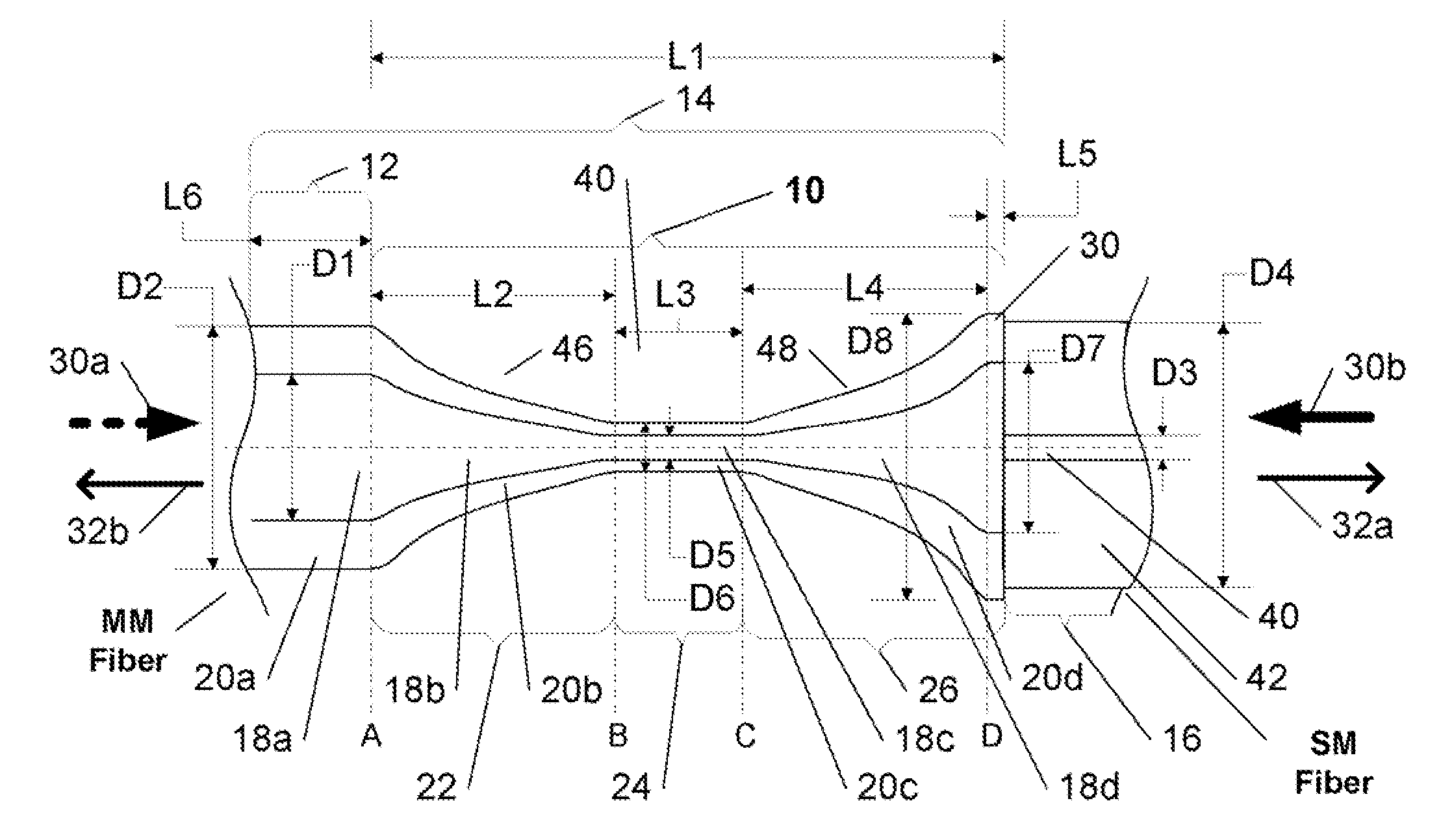
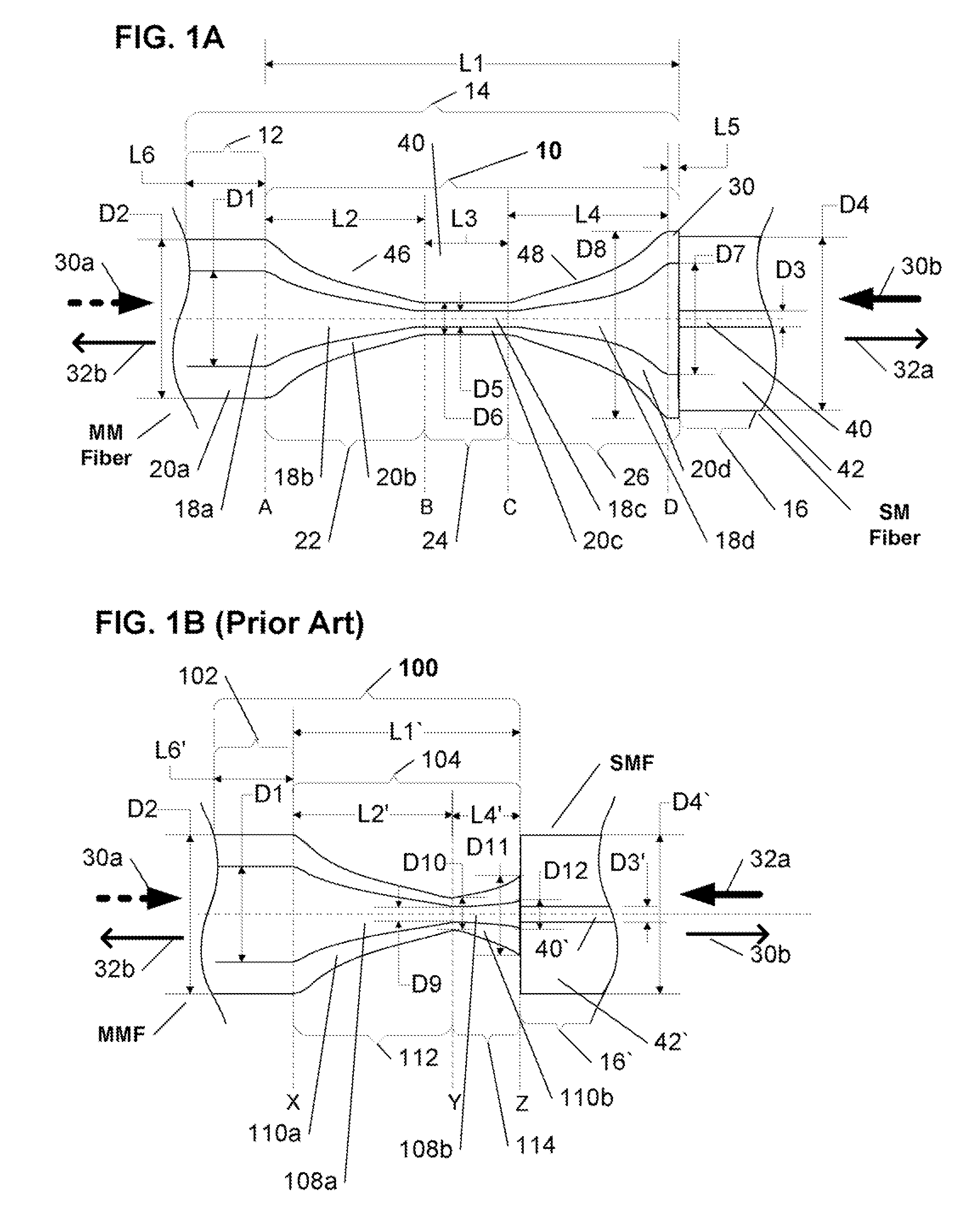
[0026]The optical fiber mode coupling device of the present invention not only addresses the flaws and shortcomings of previously known mode filters, but is also capable of selectively being utilized for fiber mode conditioning, while advantageously being configured for connection to a conventional optical fiber with a high degree of ruggedness. The inventive mode coupling device substantially only allows coupling of at least one supported fiber mode, and is preferably configured to maximize the coupling with only at least one desired fiber mode.

[0027]Advantageously, the inventive mode coupling device is capable of performing the functions of a mode filter for a signal entering its first end from a multimode optical fiber, or serving as a mode conditioner for a signal entering its opposite second end from a single mode optical fiber. Accordingly, in one practical application thereof, the inventive mode coupling device functions as a mode filter by maximizing the coupling between at ...


PUM

PropertyMeasurementUnit
refractive indicesaaaaaaaaaa
refractive indexaaaaaaaaaa
core diameteraaaaaaaaaa

Abstract

An optical fiber mode coupling device, capable of being readily connected to a conventional optical fiber with a high degree of ruggedness, is provided. The inventive mode coupling device only allows transmission of at least one supported fiber mode therethrough, and is preferably configured to maximize the coupling, of at least one desired fiber mode, to the at least one supported fiber mode. Advantageously, the inventive mode coupling device is capable of performing the functions of a mode filter for the signal entering its first end, or serving as a mode conditioner for the signal entering its opposite second end. Thus, in one practical application thereof, the novel mode coupling device functions as a mode filter by maximizing the coupling between at least one desired fiber mode of a multi-mode input signal entering the device's first end, and at least one supported mode of the device, to produce an output signal at the device's second end that comprises at least one predetermined fiber mode, corresponding to at least one desired fiber mode. In another practical application thereof, the novel mode coupling device functions as a mode conditioner by maximizing the coupling between an input signal, comprising at least one predetermined fiber mode, that enters the device's second end, and, and at least one supported mode of the device, to produce an output signal at the device's first end that comprises at least one desired fiber mode, corresponding to a conditioned at least one predetermined fiber mode.

Description

FIELD OF THE INVENTION[0001]The present invention relates generally to mode coupling devices, and more particularly to an in-fiber optical fiber mode coupling device that only permits coupling of at least one supported fiber mode with only at least one desired fiber mode, that is configured to maximize that coupling, and that is capable of connection to a conventional optical fiber with sufficient ruggedness to enable commercial / industrial utilization thereof without additional external coupling components.BACKGROUND OF THE INVENTION[0002]Mode filter devices (hereinafter “mode filters”) are in common use in many modern digital communication systems that utilize optical fibers for data transmission. At the most basic level, a typical digital communication system that utilizes multimode fibers, includes a transmitter for transmitting an optical signal over a multimode fiber connected thereto, and also includes at least one receiver, each for receiving an optical signal of at least one...

Claims


Application Information

Patent Timeline
Patent Type & Authority Applications(United States)
IPC IPC(8): G02B6/27B29D11/00
CPCB29D11/0075G02B6/305G02B6/264G02B6/14
Inventor KOPP, VICTOR IL'CHSINGER, JONATHANCHURIKOV, VICTOR M.DRAPER, CHRISTOPHER W.CHAO, NORMANNEUGROSCHL, DANIEL
Owner CHIRAL PHOTONICS
Why Eureka
Try Eureka