Turbine unit for refrigerating/cooling air cycle
a technology of refrigerating/cooling air cycle and turbine unit, which is applied in the direction of force/torque/work measurement apparatus, instruments, lighting applications, etc., can solve the problems of reducing efficiency, imposing thrust load on bearings, and not providing sufficient energy efficiency properties, so as to increase the support force against thrust force, increase the productivity and assembly the effect of eas
- Summary
- Abstract
- Description
- Claims
- Application Information
AI Technical Summary
Benefits of technology
Problems solved by technology
Method used
Image

Examples
first embodiment
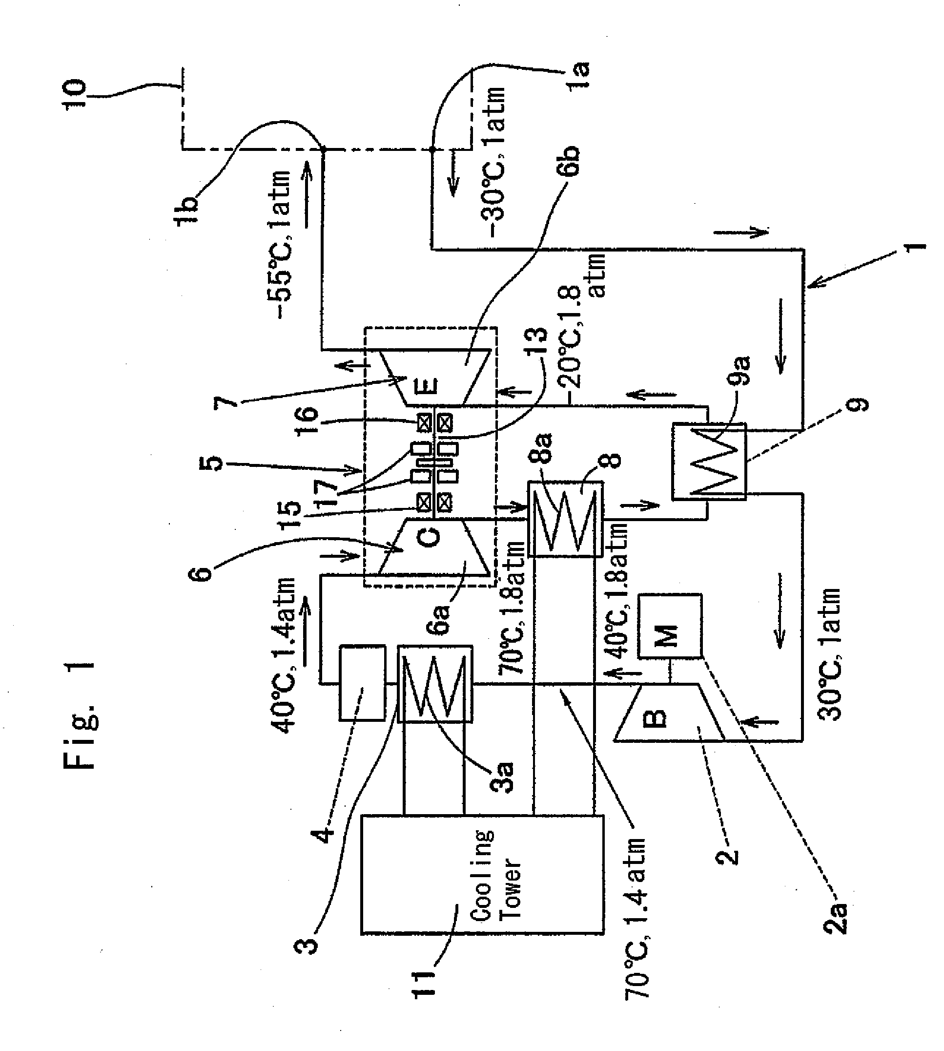
[0108]this invention is described in reference to FIGS. 1 and 2. FIG. 1 shows the entire configuration of the air cycle refrigerating / cooling system. This air cycle refrigerating / cooling system is a system for cooling air in a space to be cooled 10, such as a refrigerator, directly as a coolant and has an air circulation path 1 that reaches from an air inlet 1a to an outlet 1b, which are respective openings in the space to be cooled 10. This air circulation path 1 is provided with a pre-compressing unit 2, a first heat exchanger 3, a dehumidifier 4, a compressor 6 in a turbine unit 5 for air cycle refrigerating / cooling, a second heat exchanger 8, an intermediate heat exchanger 9 and an expansion turbine 7 in the above described turbine unit 5 in this order. The intermediate heat exchanger 9 exchanges heat between the air in the vicinity of the inlet 1a that has flown into the air circulation path 1 and the air of which the temperature rises through the compression in the rear stage ...
second embodiment
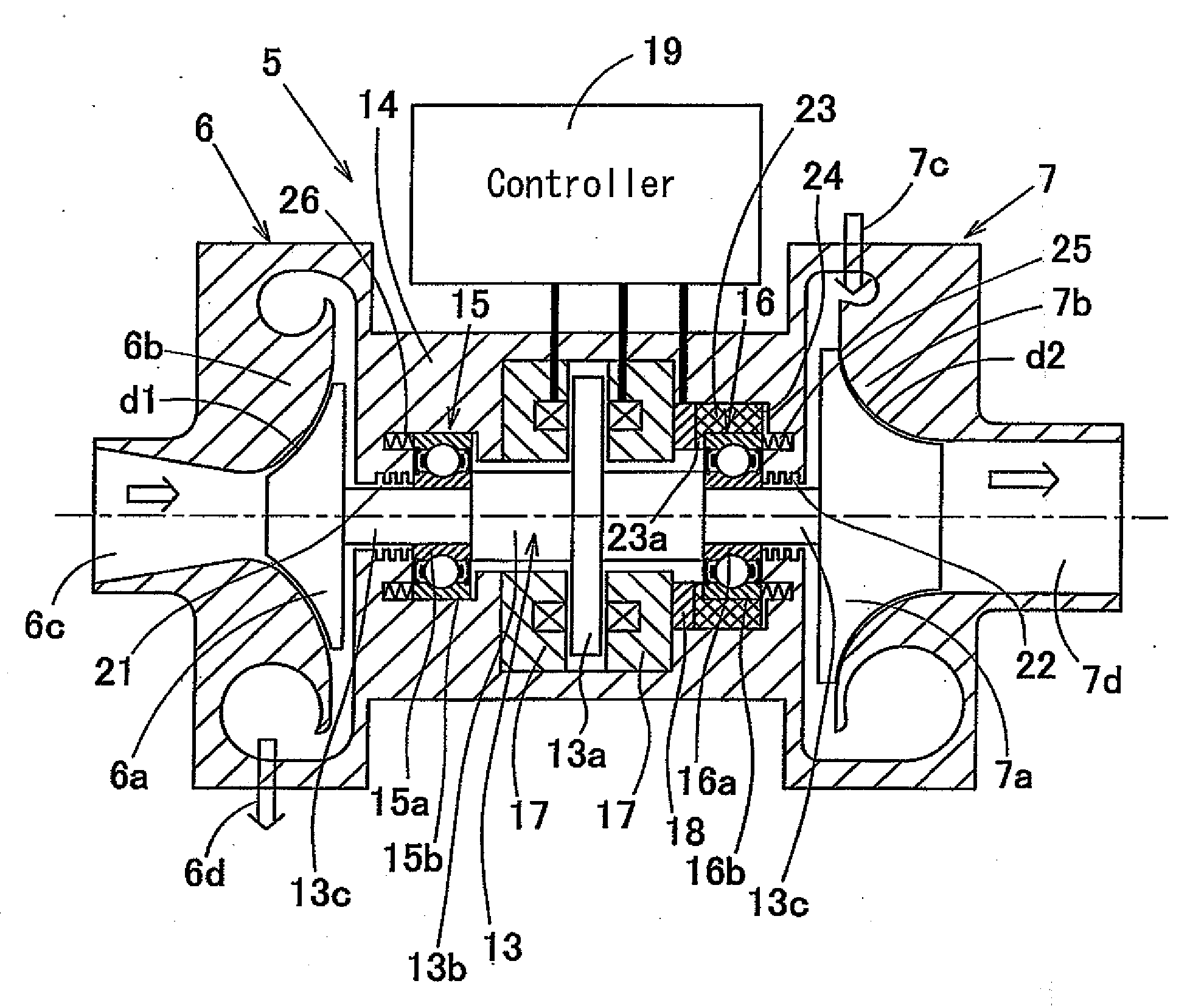
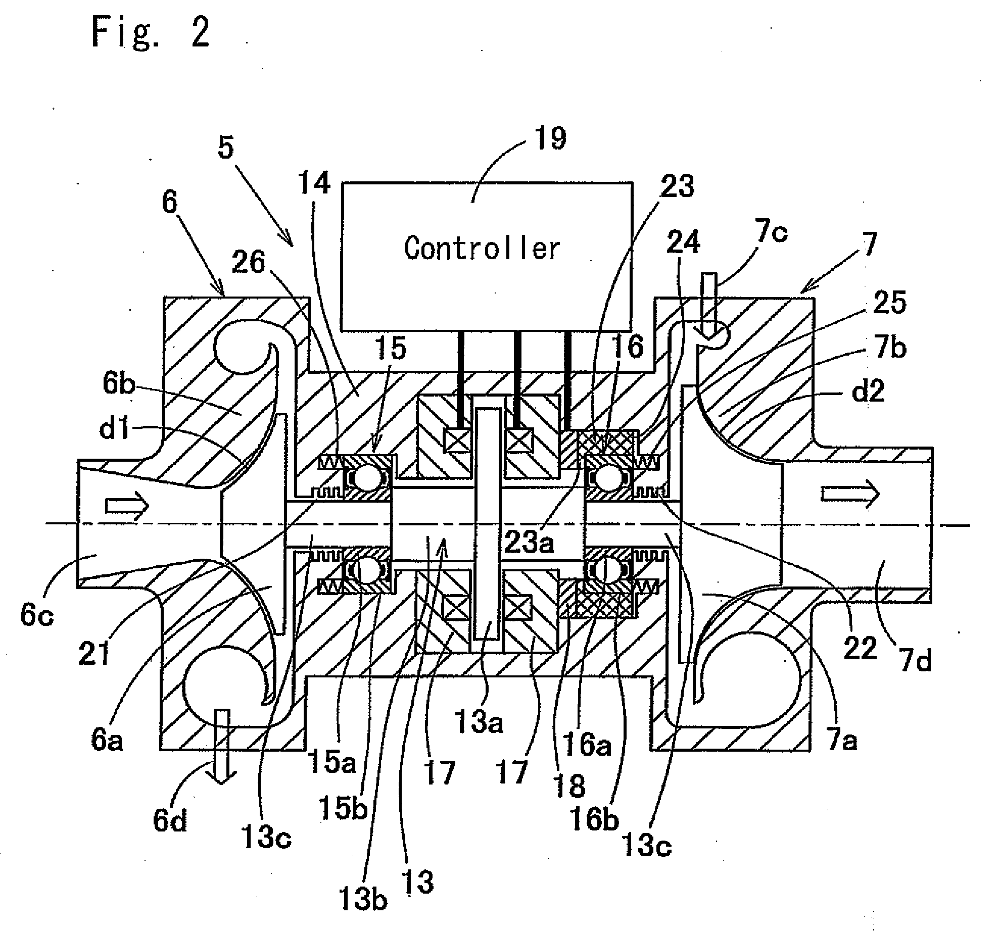
[0139]In the case of the above configuration, the arrangement of the sensor 18 and the direction of the preload applied by the resilient elements 25, 26 are opposite to that of the embodiment shown in FIG. 2, but in this second embodiment as well, the sensor 18 is arranged in the vicinity of the bearing 16 so that the thrust force applied to the bearing 16 can be directly detected. In addition, the same effects as those explained in the embodiment of FIG. 2 can be obtained.
third embodiment
[0140]In the third embodiment shown in FIG. 4, the outer ring 15b of the bearing 15 on the axial side where the sensor is not arranged is fixed to the inner periphery of a bearing housing 27, which is prepared as a separate member from the spindle housing 14. The bearing housing 27 has inward flanges respectively engaged with opposite end faces of the outer ring 15b, and is engaged in the inner diametric hole 28 provided in the spindle housing 14 moveably in the axial direction. The second resilient element 26 applies a preload to the outer ring 15b via the bearing housing 27.
PUM
 Abstract
Description
Claims
Application Information
 - Generate Ideas
- Intellectual Property
- Life Sciences
- Materials
- Tech Scout
- Unparalleled Data Quality
- Higher Quality Content
- 60% Fewer Hallucinations
Browse by: Latest US Patents, China's latest patents, Technical Efficacy Thesaurus, Application Domain, Technology Topic, Popular Technical Reports.
© 2025 PatSnap. All rights reserved.Legal|Privacy policy|Modern Slavery Act Transparency Statement|Sitemap|About US| Contact US: help@patsnap.com