S/N Ratio Measuring Method in Eddy Current Testing on Internal Surface of Pipe or Tube

a technology of eddy current testing and s/n ratio, which is applied in the direction of noise figure or signal-to-noise ratio measurement, instruments, magnetic variables, etc., can solve the problems of inability to provide reliable measurements and extremely poor working efficiency of s/n measurements, and achieve high efficiency and high reliability

Active Publication Date: 2009-05-28
NIPPON STEEL CORP
View PDF4 Cites 5 Cited by
  • Summary
  • Abstract
  • Description
  • Claims
  • Application Information

AI Technical Summary

Benefits of technology

[0036]In accordance with a method for measuring the S/N ratio in an eddy current testing on an internal surface of a pipe or tube rel...

Problems solved by technology

Therefore, even when only the prior art disclosed in Patent Document 1 or 2 is used, the above-mentioned problem that the working efficiency on the S/N measurements is extre...

Method used


Image

  • S/N Ratio Measuring Method in Eddy Current Testing on Internal Surface of Pipe or Tube
  • S/N Ratio Measuring Method in Eddy Current Testing on Internal Surface of Pipe or Tube
  • S/N Ratio Measuring Method in Eddy Current Testing on Internal Surface of Pipe or Tube

Examples


example 1

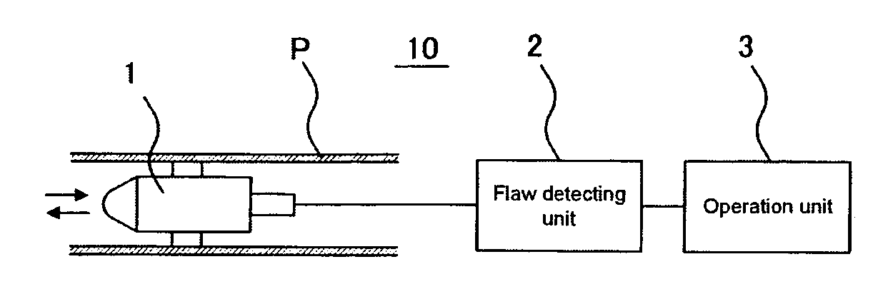
[0063]By using an eddy current testing unit having the same structure as that shown in FIG. 1, the S / N ratio defined by the above-mentioned Equation (2) was automatically measured under flaw detecting conditions shown in the following Table 1.

TABLE 1Sampling Rate500points / secFlaw Detecting Probe Velocity305mm / secDistance between Sampling Points0.61mmLength of Tube20000mm

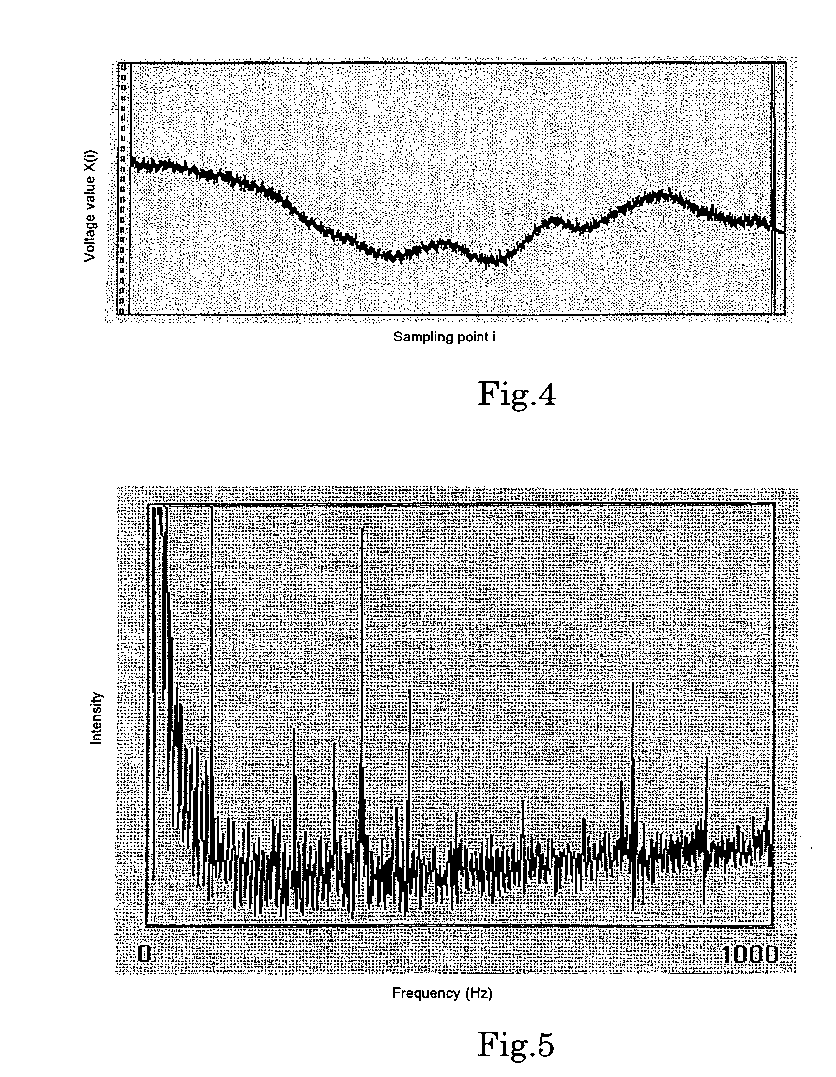
[0064]Here, upon measuring the voltage value D of an eddy current signal corresponding to an artificial flaw, a tube having through holes, each having 0.66 mm in diameter, formed at four positions in a circumferential direction with pitches of 90° as artificial flaws, was used. Moreover, upon measuring the noise voltage value V1, a tube, made of the same material with the same dimension as those of the above-mentioned tube, with no artificial flaws formed therein, was used, and the eddy current testing was carried out over the entire length of the tube. With respect to the method for excluding a low-frequency compone...

example 2

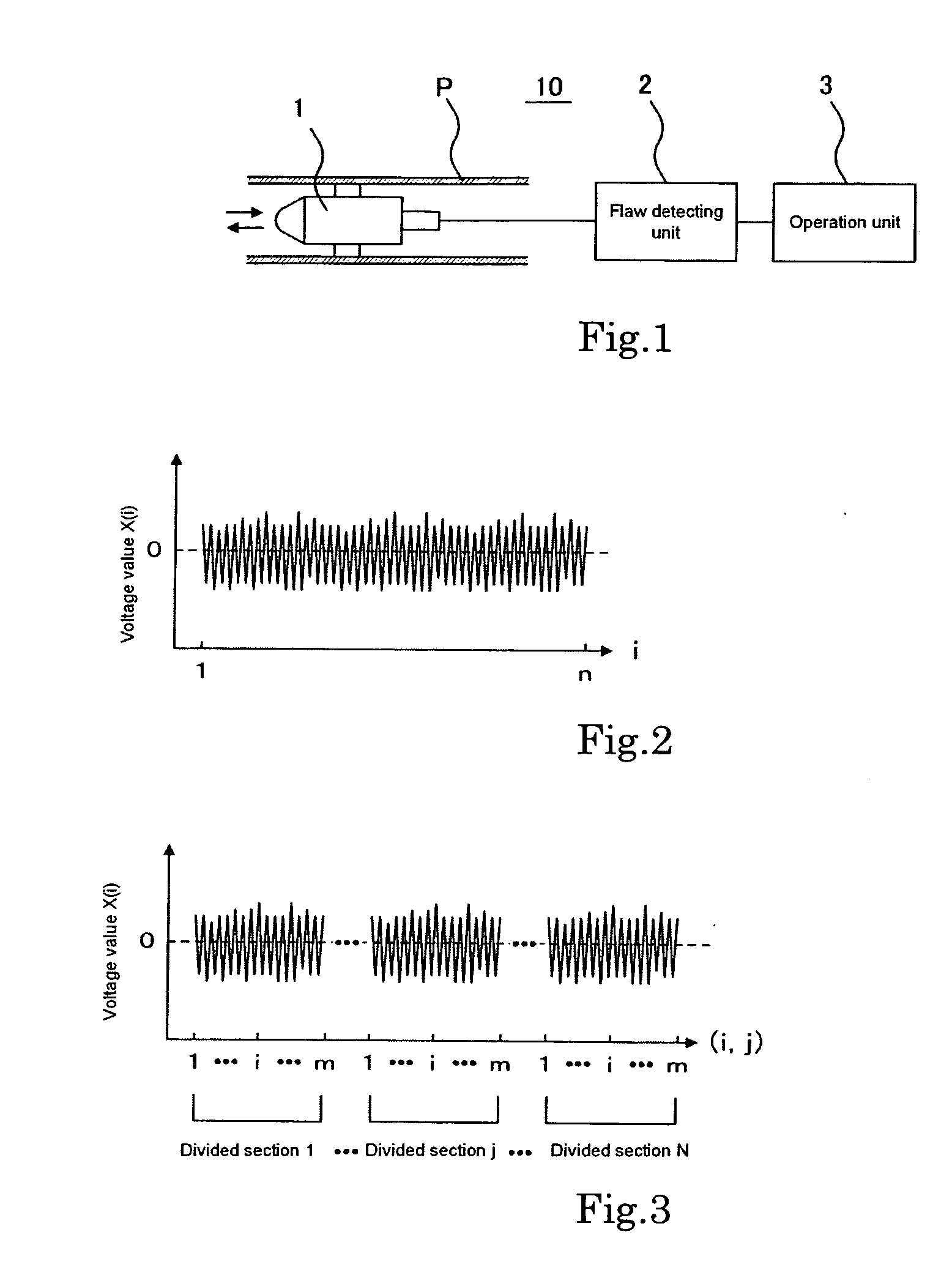
[0066]By using an eddy current testing unit having the same structure as that shown in FIG. 1, the S / N ratio defined by the above-mentioned Equation (4) was automatically measured under flaw detecting conditions shown in the following Table 1. Here, the same artificial flaws formed in the tube and the same cut-off frequency as those of Example 1 were used. Moreover, upon measuring the noise voltage value V2, the number of sampling points of respective sections into which the signal waveform data were divided was set to about 305 mm when converted into the length, and the eddy current testing was carried out over the entire length of the tube in the same manner as in Example 1.


PUM


Abstract

A method in accordance with the present invention includes the steps of: separating an eddy current signal into an X-axis component and a Y-axis component to obtain signal waveform data of the respective components; excluding predetermined low-frequency components respectively from the respective signal waveform data thus obtained; calculating a noise voltage value V1 defined by the following Equation (1) based upon voltage values X(i) and Y(i) of the signal waveform data of the X-axis component and the Y-axis component from which the low-frequency components have been excluded; and calculating an S/N ratio by dividing a voltage value D of an eddy current signal corresponding to a predetermined artificial flaw by the noise voltage value V1:
V1=π/n·i=1n(X(i)2+Y(i)2)1/2(1)
where n represents the number of samplings of the signal waveform data.

Description

TECHNICAL FIELD[0001]The present invention relates to a method for measuring an S / N ratio (ratio of flaw signal to noise) in an eddy current testing on an internal surface of a pipe or tube that is carried out, for example, upon producing a pipe or tube for use as a heat exchanger pipe or tube arranged in a steam generator of a nuclear reactor, which provides effective measurements on the S / N ratio with high reliability. Hereinafter “pipe or tube” is generally referred to as “tube” when deemed appropriate.BACKGROUND ART[0002]Conventionally, a regular inspecting process for heat exchanger tubes arranged in a steam generator of a PWR-type nuclear reactor is carried out by using an eddy current testing on an internal surface of a tube. More specifically, the process is carried out as follows: When a flaw detecting coil is inserted onto an internal surface of a tube, with an AC voltage applied thereto, an AC magnetic field is generated so that an eddy current is induced on the tube inte...

Claims


Application Information

Patent Timeline
IPC IPC(8): G01R29/26G01R23/16
CPCG01N27/9046G01N27/90
Inventor KINOMURA, SHOJINAKAO, YOSHIYUKIKODAI, TOSHIYANISHIYAMA, SHUGO
Owner NIPPON STEEL CORP
Why Eureka
Try Eureka