
Stray light reduction in imaging reader

a technology of imaging reader and stray light, which is applied in the field of stray light reduction in imaging reader, can solve the problems of ghost images, degrade the performance of readers, and reduce the contrast of the image of the symbol being read, so as to reduce the amount of stray light directed, the effect of brightening the intensity and shortening the tim

Inactive Publication Date: 2009-06-04
SYMBOL TECH INC
View PDF16 Cites 9 Cited by
  • Summary
  • Abstract
  • Description
  • Claims
  • Application Information

AI Technical Summary

Benefits of technology

[0007]The imager is preferably associated with an illuminator for illuminating the indicia with illumination light to enable an image of the indicia to be acquired, preferably in a very short period of time, for example, on the order of 500 microseconds, so that the indicia image is not blurred even if there is relative motion between the imager and the indicia. The illumination light is preferably brighter in intensity than that of ambient illumination, especially close to the window. The illuminator preferably includes a single light source or light emitting diode (LED), but may include a plurality of light sources or LEDs, and a lightpipe constituted of an optical material and operative for optically guiding the illumination light from the light source(s) toward the indicia. The imager is operative for sensing the illumination light scattered or reflected from the indicia.
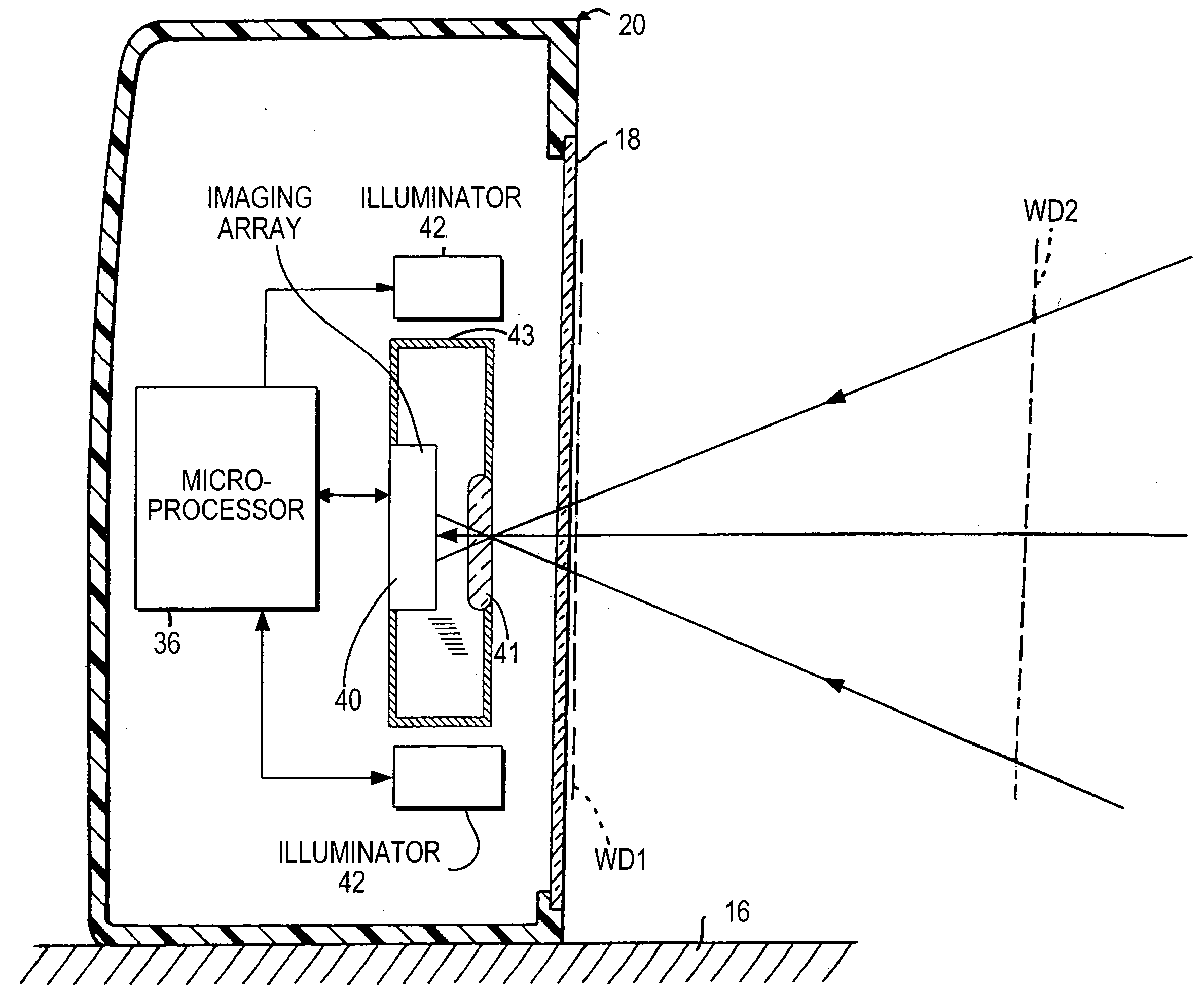
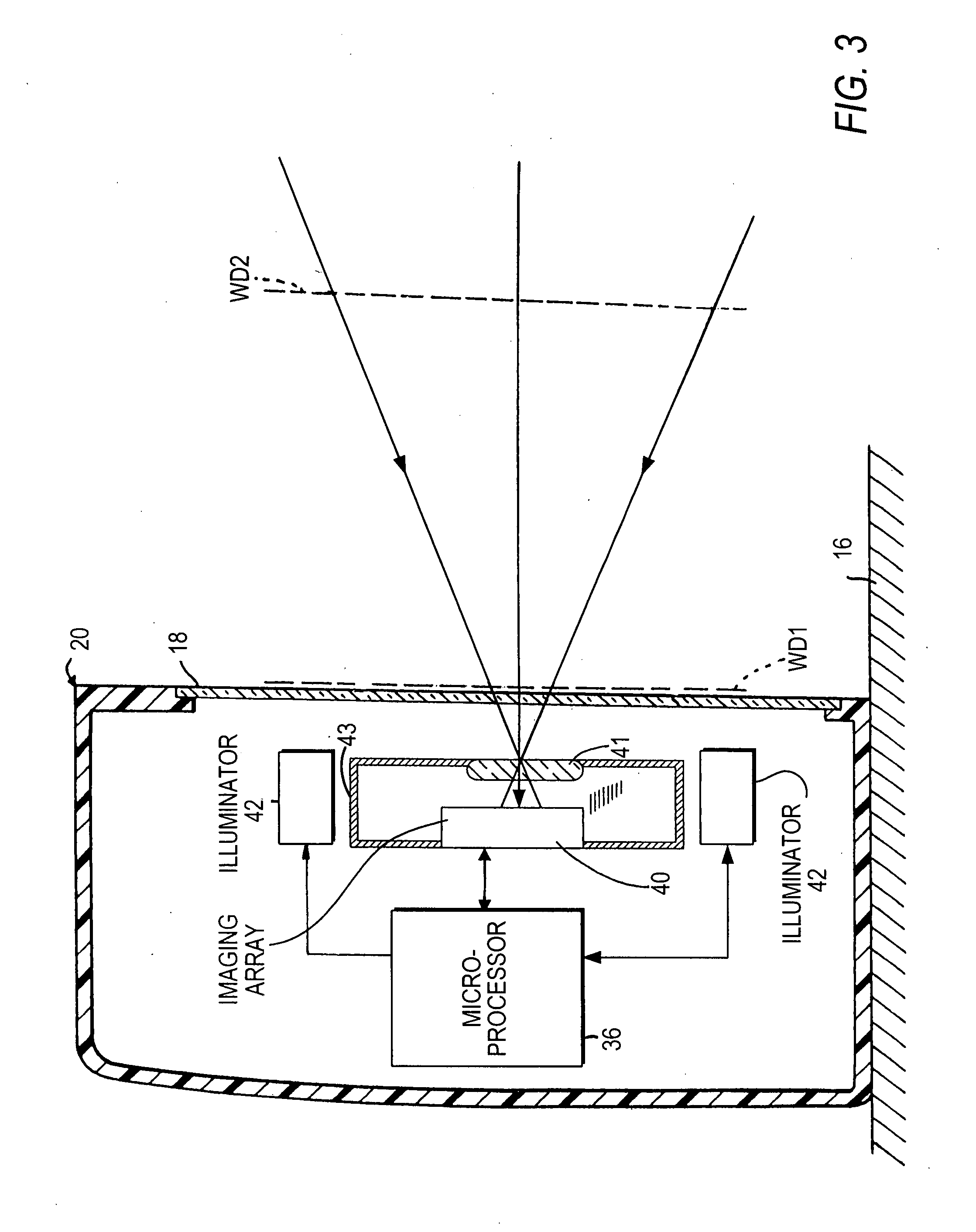
[0008]In accordance with this invention, a baffle is provided for reducing an amount of stray light directed to the imager. The stray or unwanted light arises from the above-described ambient and illumination light. The baffle effectively rejects any ambient and / or illumination light incident on the lens holder at an angle that would otherwise scatter and / or reflect towards the imager and create ghost images and low contrast images of the indicia being read. The baffle reduces the formation of such ghost images and low contrast images, thereby improving reader performance.
[0009]The baffle is advantageously integrated into the lens holder, thereby making for a compact design. A light-absorptive coating is applied on the baffle and the holder. The integral baffle reduces assembly and manufacturing costs and promotes the use of the reader as a miniature component or subsystem in a non-stand-alone apparatus, or a myriad of other apparatuses, such as a telephone, a mobile computer, or the like, where space is at a premium.
[0011]Another feature of the present invention resides, briefly stated, in a method of electro-optically reading indicia, the method being performed by capturing light from the indicia over a field of view during the reading with a solid-state imager having an array of image sensors, by spacing an optical lens away from the imager along an optical axis, by holding the optical lens with a holder, and by reducing an amount of stray light directed to the imager by integrating a baffle with the holder.

Problems solved by technology

Stray light often causes ghost images, as well as lowering the contrast of the image of the symbol being read.
Such stray light degrades reader performance.
However, most black coatings are not completely light absorptive and, in many cases, exhibit wide variations in their diffuse and specular reflection characteristics.

Method used


Image

  • Stray light reduction in imaging reader
  • Stray light reduction in imaging reader
  • Stray light reduction in imaging reader

Examples


Embodiment Construction

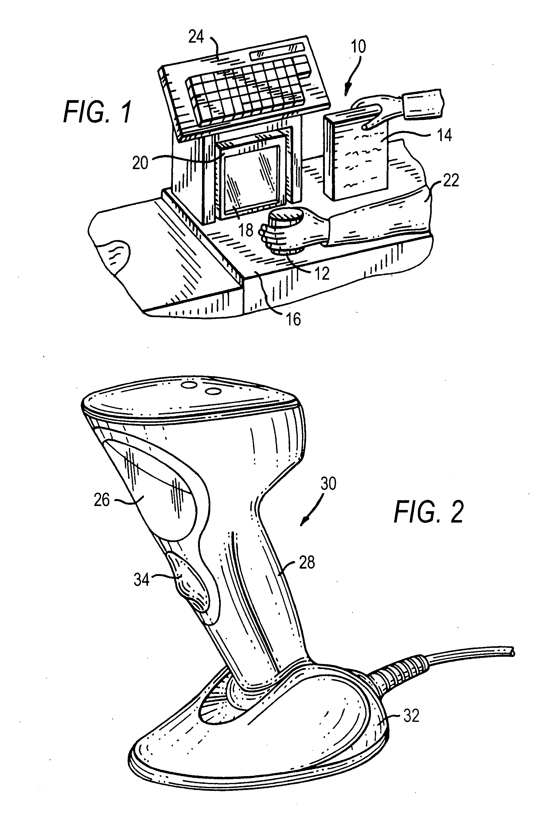
[0018]Reference numeral 10 in FIG. 1 generally identifies an electro-optical reader in a workstation mode for processing transactions and mounted on a checkout counter at a retail site at which products, such as a can 12 or a box 14, each bearing a target symbol, are processed for purchase. The counter includes a countertop 16 across which the products are slid at a swipe speed past a generally vertical window 18 of a box-shaped imaging reader 20 mounted on the countertop 16. A checkout clerk or operator 22 is located at one side of the countertop, and the reader 20 is located at the opposite side. A cash / credit register 24 is located within easy reach of the operator. The reader 20 is portable and lightweight and may be picked up from the countertop 16 by the operator 22, and the window 18 may be aimed at a symbol preferably on a product too heavy or too large to be easily positioned on the countertop in front of the reader in the workstation mode.

[0019]Reference numeral 30 in FIG....


PUM


Abstract

A solid-state imager and an optical lens in an imaging reader for electro-optically reading indicia are operative for capturing light from the indicia over a field of view during reading. A holder holds the optical lens. A baffle is integrated with the holder, for reducing the image-degrading effects of stray light directed to the imager.

Description

BACKGROUND OF THE INVENTION[0001]Various electro-optical readers have previously been developed for reading both one- and two- dimensional bar code symbols appearing on a label or surface of a product or target. The symbol itself is a coded pattern of indicia. An example of a one-dimensional bar code symbol is a Universal Product Code (UPC) symbol. Examples of two-dimensional symbols are Code 49, as described in U.S. Pat. No. 4,794,239, and PDF417, as described in U.S. Pat. No. 5,304,786. Generally, the readers electro-optically transform graphic indicia of the symbols into electrical signals, which are decoded into alphanumeric characters. The resulting characters describe the target and / or some characteristic of the target with which the symbol is associated. Such characters typically comprise input data to a data processing system for applications in point-of-sale processing, inventory control, article tracking and the like.[0002]A moving laser beam electro-optical reader has bee...

Claims


Application Information

Patent Timeline
Patent Type & Authority Applications(United States)
IPC IPC(8): G06K7/10
CPCG06K7/10792G06K7/10722
Inventor LIU, RONGYU, MING
Owner SYMBOL TECH INC
Learn More