Spindle motor having a fluid dynamic bearing system and a stationary shaft

a technology of fluid dynamic bearing and spindle motor, which is applied in the direction of sliding contact bearings, instruments, record information storage, etc., can solve the problems of complex construction, especially the sealing of a spindle motor having a stationary shaft and a fluid dynamic bearing system open at both ends, and achieves low cost, easy construction, and easy machineability.

Active Publication Date: 2009-06-04
MINEBEAMITSUMI INC
View PDF16 Cites 47 Cited by
  • Summary
  • Abstract
  • Description
  • Claims
  • Application Information

AI Technical Summary

Benefits of technology

[0009]In a preferred embodiment of the invention, the bearing system merely comprises a total of four mechanical components, three components being stationary components and only one rotating, mechanical rotor component taking the form of a hub / bearing bush arrangement being provided. Thanks to the small number of parts, the bearing system can be very easily constructed and, in particular, the parts can be made and machined relatively easily and at low cost.

Problems solved by technology

The construction, and especially the sealing of a spindle motor having a stationary shaft and a fluid dynamic bearing system open at both ends are generally more complex than for a spindle motor having a rotating shaft.
Particularly the manufacture of the bearing components of the fluid bearing, such as the bearing bush and the shaft, having tolerances in the sub-micrometer range and the precise and stable connection of the small individual parts of the motor create various problems (e.g. axial runout of the rotor component / change due to external stress) for the small form factors (2.5, 1.8 or 1 inch drives) that are now finding increasing application.

Method used


Image

  • Spindle motor having a fluid dynamic bearing system and a stationary shaft
  • Spindle motor having a fluid dynamic bearing system and a stationary shaft
  • Spindle motor having a fluid dynamic bearing system and a stationary shaft

Examples


Embodiment Construction

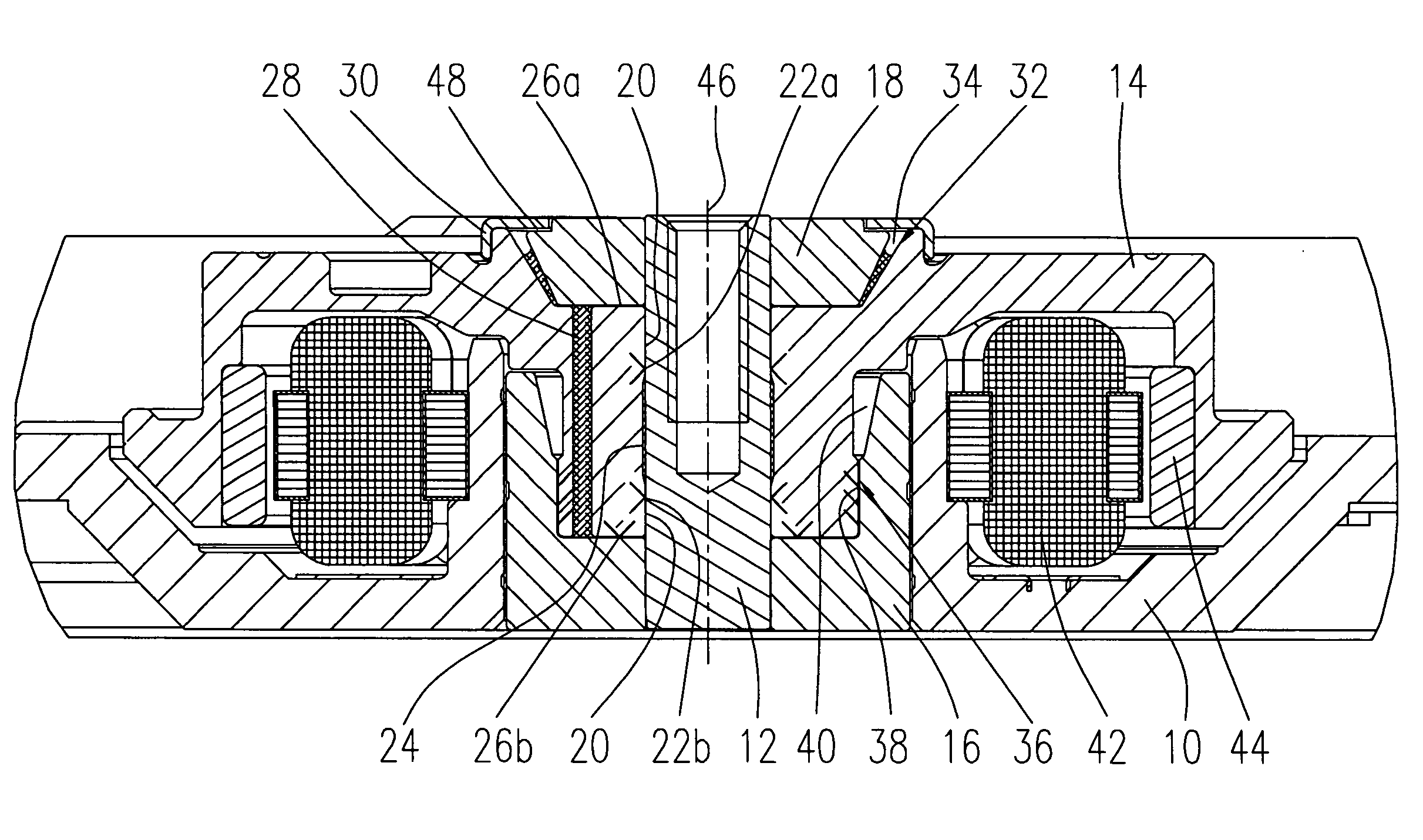
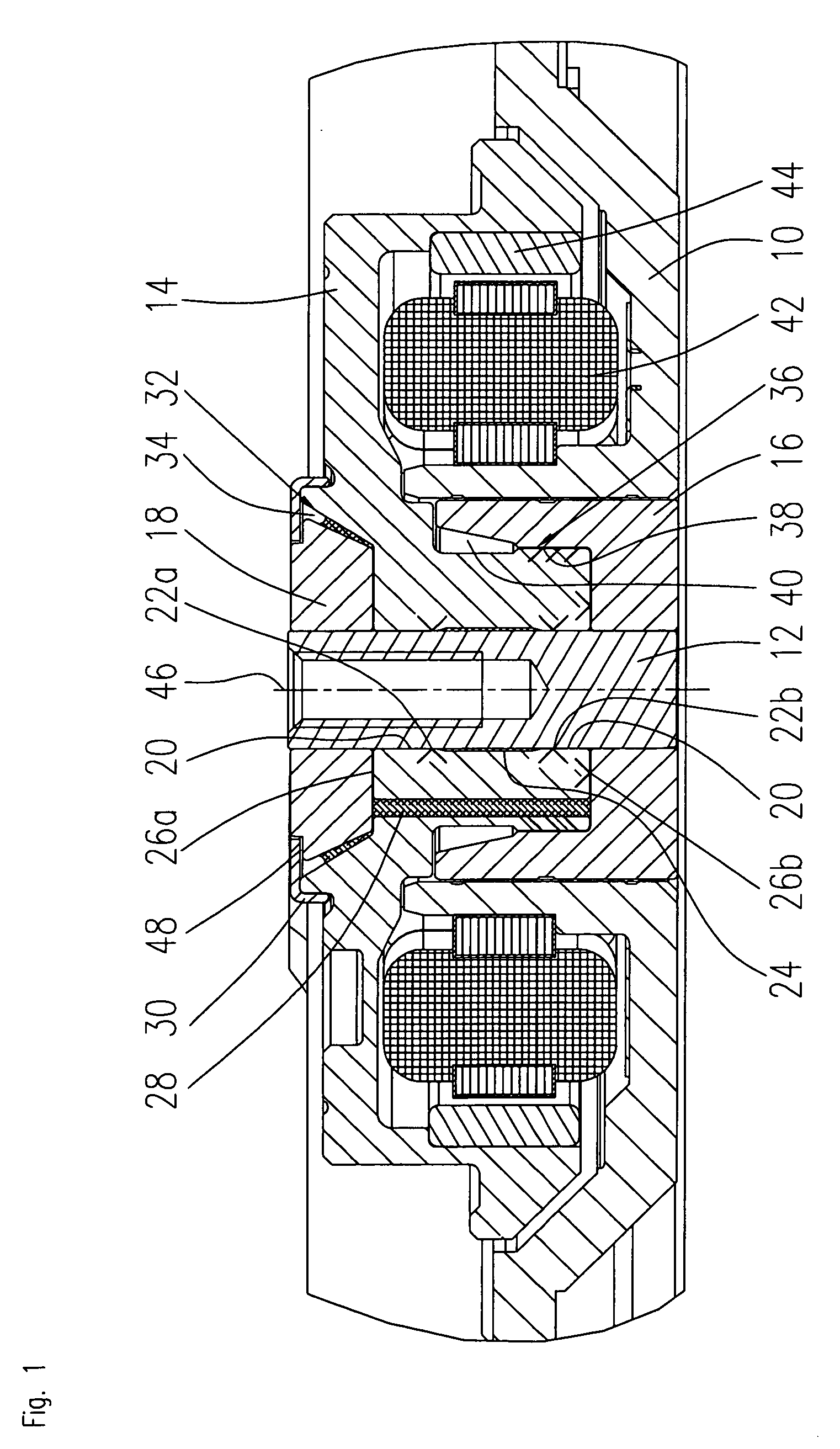
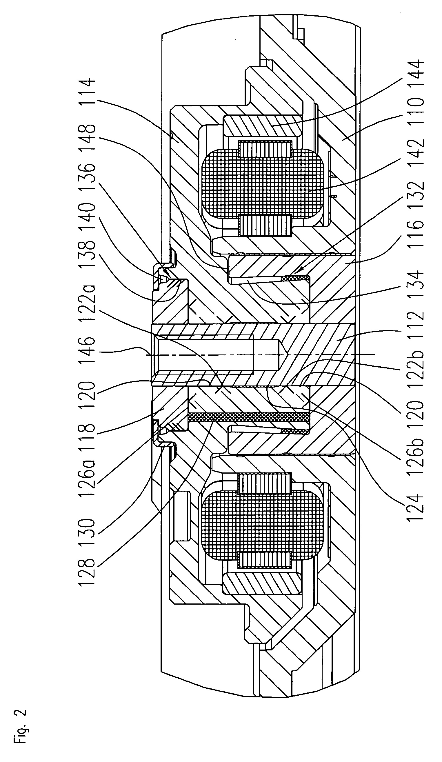
[0024]FIGS. 1 to 7 show various embodiments of spindle motors according to the invention, all the illustrated spindle motors essentially having the same basic construction. The spindle motors could be used for driving the storage disks of a hard disk drive.

[0025]The spindle motor according to FIG. 1 comprises a baseplate 10 that has a substantially central cylindrical opening in which a first bearing component 16 is accommodated. The first bearing component 16 is approximately cup-shaped in form and comprises a central opening in which the shaft 12 is fixed. A second bearing component 18 is disposed at an upper end of the stationary shaft 12, the second bearing component 18 being preferably annular in shape. The above-mentioned components form the stationary components of the spindle motor. At its upper end, the shaft 12 may additionally be fixed to the housing of the spindle motor. The spindle motor comprises a single-piece rotor component 14 that is disposed in a space formed by t...


PUM


Abstract

The invention relates to a spindle motor having a fluid dynamic bearing system that contains a rotor component taking the form of an integrated hub / bearing bush arrangement which encloses a straight, stationary shaft, which in turn is connected at both its ends to axially aligned bearing components, formed in such a way that they seal the fluid dynamic bearing system formed between the shaft and the rotor component and open at both ends. The open ends of the bearing gap are sealed by capillary seals or pumping seals or a combination of capillary and pumping seal.

Description

BACKGROUND OF THE INVENTION[0001]The invention relates to a spindle motor having a fluid dynamic bearing system and a stationary shaft. These kinds of spindle motors are used, for example, for driving disk drives.DESCRIPTION OF THE PRIOR ART[0002]Spindle motors having fluid dynamic bearing systems can essentially be divided into two different groups, that is to say, into two different designs: motors having a rotating shaft and a bearing system that is usually open at only one end (e.g. a single plate design) and motors having a stationary shaft. A significant advantage afforded by spindle motors having a stationary shaft is the possibility of not only fixing the spindle motor at one end of the stationary shaft to the baseplate of a housing, but also of connecting it at the other end of the shaft, for example, to a housing cover. These types of motors thereby acquire appreciably greater structural stiffness, making them particularly suitable for use, for example, in hard disk drives...

Claims


Application Information

Patent Timeline
Patent Type & Authority Applications(United States)
IPC IPC(8): H02K5/167
CPCG11B19/2036H02K5/1677F16C17/107F16C33/745F16C2370/12
Inventor DRAUTZ, FRANKBAUER, MARTIN
Owner MINEBEAMITSUMI INC
Why Eureka
Try Eureka