Electric power steering system

a technology of electric power steering and power steering shaft, which is applied in the direction of motor/generator/converter stopper, dynamo-electric converter control, transportation and packaging, etc., can solve the problems of increasing the cost of electric power steering power source, and increasing the cost of electric power steering. , to achieve the effect of suppressing the cost increas

Inactive Publication Date: 2009-06-04
TOYOTA JIDOSHA KK
View PDF2 Cites 25 Cited by
  • Summary
  • Abstract
  • Description
  • Claims
  • Application Information

AI Technical Summary

Benefits of technology

[0023]By virtue of this configuration, charging to the low-voltage battery becomes possible, and a predetermined voltage can be maintained even when the charging system becomes anomalous.
[0024]Notably, in this case, in order to prevent breakage of the step-up circuit of the secondary power supply circuit due to overcurrent, a switching element may be provided in the secondary power supply line and controlled such that the on period of this switching element is restricted. In particular, when the second switching element of the step-up circuit is used as that switching element, an increase in cost can be suppressed.

Problems solved by technology

However, the conventional apparatus requires a changeover device such as a changeover switch for selectively using power supplied from the two batteries, resulting in an increase in cost.
However, when a system using a high-voltage-type battery as a power source is configured, provision of another high-voltage-type battery as a backup for power failure becomes necessary.
Therefore, cost of a power source for an electric power steering increases considerably, which is unfavorable.

Method used


Image

  • Electric power steering system
  • Electric power steering system
  • Electric power steering system

Examples


first embodiment

[0058]FIG. 4 shows a power supply control routine according to a The power supply control routine is stored in ROM of the power supply control apparatus 90 in the form of a control program, and is repeatedly executed at short intervals.

[0059]The power supply control routine is started after the relays 54 and 64 are turned on as a result of an unillustrated ignition switch being turned on.

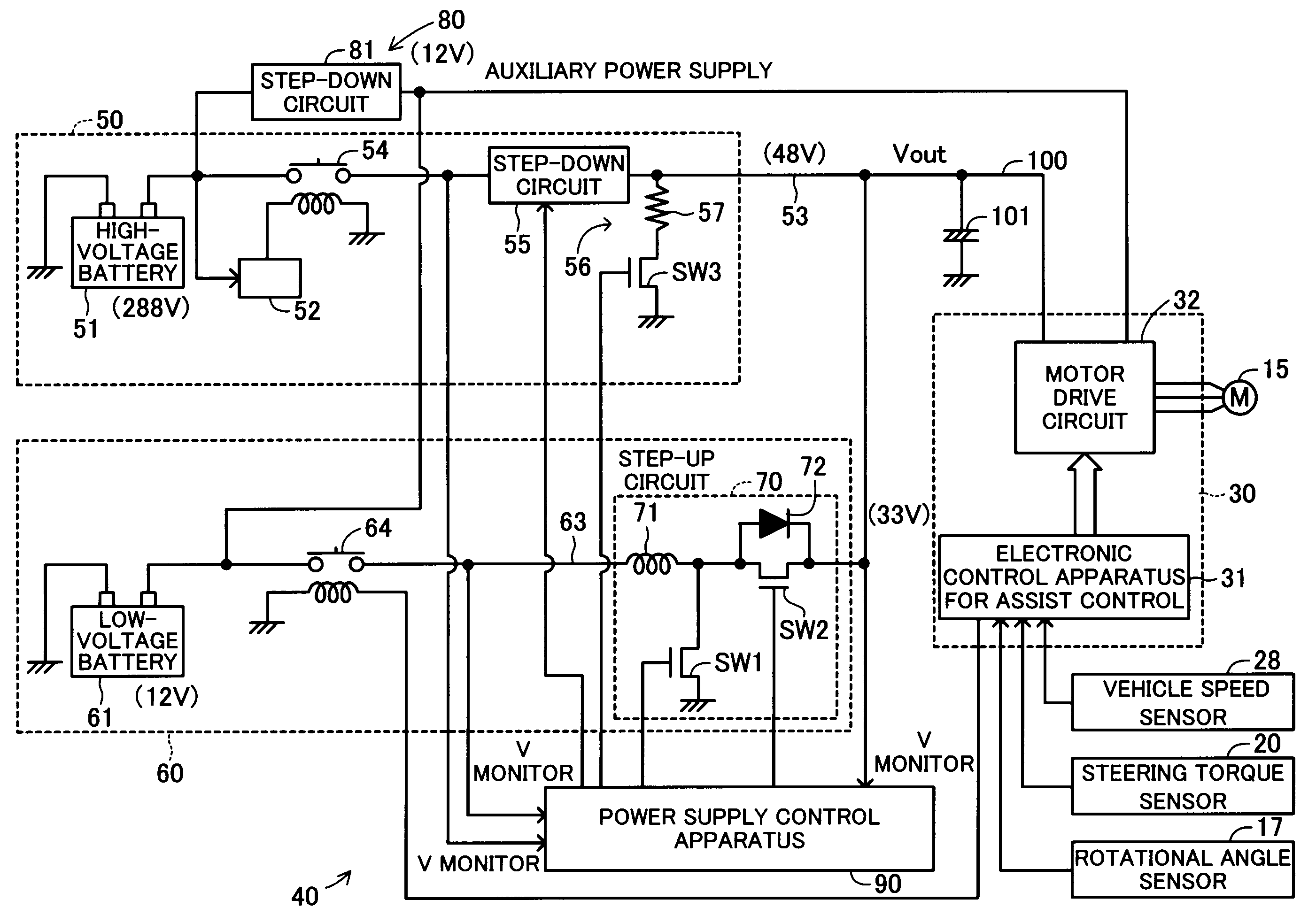
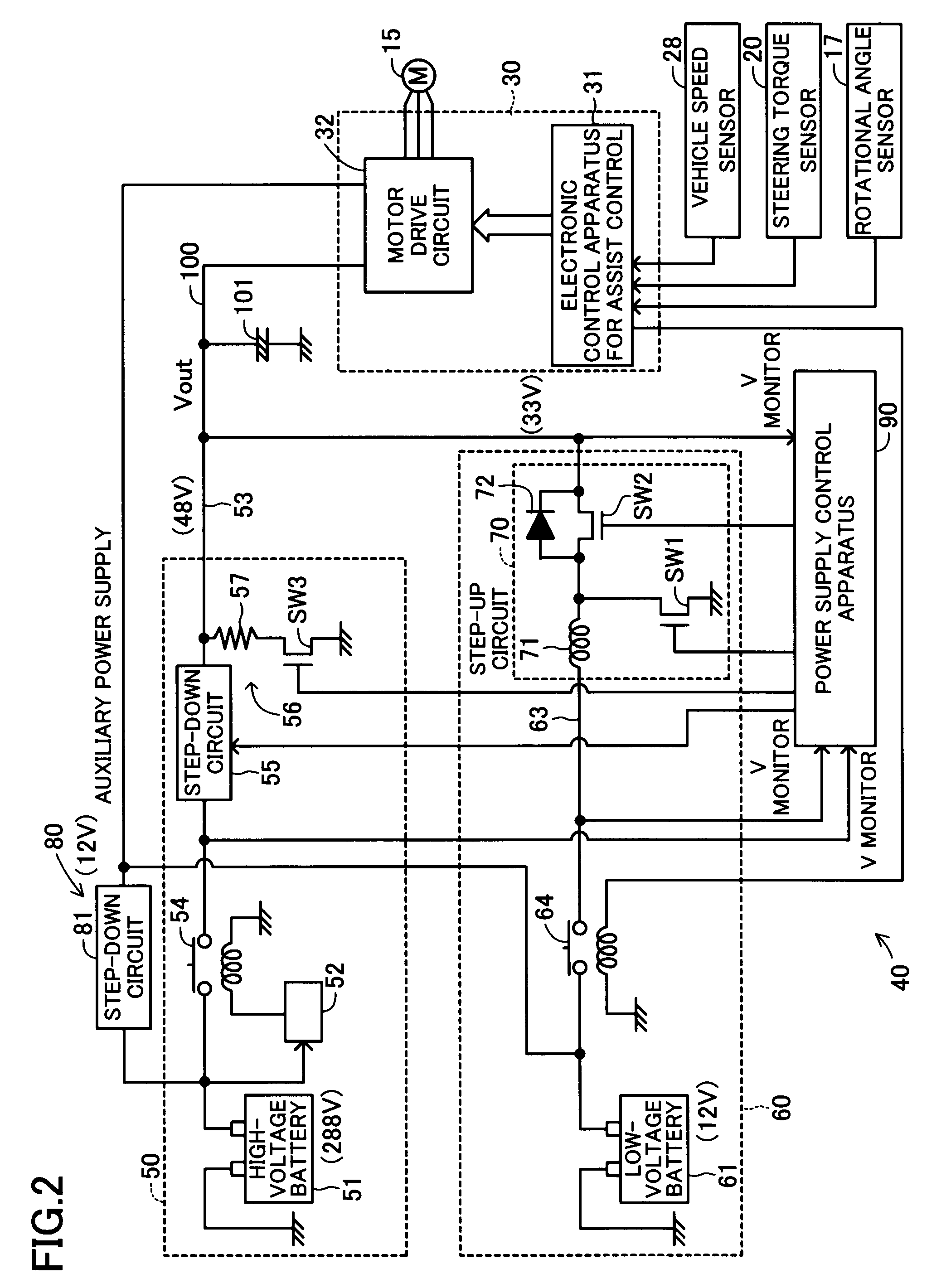
[0060]First, in step S1, the output voltage Vout is detected, and a determination is made as to whether or not the detected voltage is higher than a regeneration determination voltage VK1 (e.g., 50 V). This determination processing is performed so as to determine whether or not regenerative power is generated from the electric motor 15. The regeneration determination voltage VK1 is set such that when regenerative power is generated, the output voltage Vout exceeds the regeneration determination voltage VK1.

[0061]When regenerative power is not generated (S1: No), in step S2 subsequent to step S1, a ...

second embodiment

[0073]FIG. 5 shows the power supply control routine according to the The power supply control routine is stored in the ROM of the power supply control apparatus 90 in the form of a control program, and is repeatedly executed at short intervals.

[0074]Since the processing of step S11 to S14 is identical with the processing of step S1 to S4 of the first embodiment shown in FIG. 4, only a simplified description of the processing of step S11 to S14 will be provided.

[0075]When in step S11 the detected output voltage Vout is not higher a regeneration determination voltage VK1 (e.g., 50 V), the power supply control apparatus 90 determines that regenerative power is not generated, and proceeds to step S12 so as to determine whether or not the output voltage Vout is lower than the rated output voltage V2H (target voltage: 33 V) of the secondary power supply circuit 60. When the primary power supply circuit 50 operates normally, a “No” determination is made. In this case, since supply of elec...

third embodiment

[0081]Next, there will be described a power supply control routine which processing is performed by the power supply control apparatus 90.

[0082]FIG. 6 shows the power supply control routine according to the third embodiment. The power supply control routine is stored in the ROM of the power supply control apparatus 90 in the form of a control program, and is repeatedly executed at short intervals.

[0083]The present power supply control routine is started after the relays 54 and 64 are turned on as a result of the unillustrated ignition switch being turned on.

[0084]When the present power supply control routine is started, in step S21, the output voltage Vout is first detected, and a determination is made as to whether or not the detected voltage is higher than a regeneration determination voltage VK1 (e.g., 50 V). When the detected voltage is higher than the regeneration determination voltage VK1, the power supply control apparatus 90 determines that the electric motor 15 is generati...


PUM


Abstract

In a power supply apparatus 40, a power supply circuit is formed by a primary power supply circuit 50 which includes a high-voltage battery 51 and a step-down circuit 55 for stepping down the voltage of the high-voltage battery 51, and a secondary power supply circuit 60 which includes a low-voltage battery 61 and a step-up circuit 70 for stepping up the voltage of the low-voltage battery 61. The primary power supply circuit 50 and the secondary power supply circuit 60 are connected in parallel. An output voltage of the secondary power supply circuit 60 is set to be lower than an output voltage of the primary power supply circuit 50. When the output voltage of the primary power supply circuit 50 becomes lower than a target voltage of the secondary power supply circuit 60, the voltage stepped-up by the step-up circuit 70 is supplied to a motor drive circuit 32. Accordingly, power supply backup of an electric power steering apparatus can be performed as low cost.

Description

TECHNICAL FIELD[0001]The present invention relates to an electric power steering apparatus which includes an electric motor for applying steering force to steerable wheels in accordance with rotational operation of a steering wheel, and more particularly, to a power supply apparatus of such an electric power steering apparatus.BACKGROUND ART[0002]A conventional electric power steering apparatus of such a type includes an electric motor for applying steering assist force to rotational operation of a steering wheel, and is designed to adjust the assist force through power supply control which changes the amount of current flowing through the electric motor.[0003]Such an electric power steering apparatus uses a battery as a power source. In consideration of anomaly of a power supply line, an apparatus disclosed in Japanese Patent Application Laid-Open (kokai) No. 2004-17732 includes two batteries; i.e., a main battery and an auxiliary battery, which are of the same voltage. The apparat...

Claims


Application Information

Patent Timeline
Patent Type & Authority Applications(United States)
IPC IPC(8): H02P1/00
CPCB62D5/046H02J2001/008H02J1/08H02J1/082
Inventor KASAI, EIJIFUJINORI, YOICHISAITO, TAKATOSHIYAMASHITA, MASAHARUYAMAZAKI, IPPEIFUJITA, SHUJI
Owner TOYOTA JIDOSHA KK
Why Eureka
Try Eureka