Synchronous rectification

a rectifier controller and rectification technology, applied in the direction of dc-dc conversion, power conversion systems, climate sustainability, etc., can solve the problems of sampling errors, disadvantages, and vsub>f /sub>may become a source of errors

Active Publication Date: 2015-12-03
POWER INTEGRATIONS INC
View PDF3 Cites 12 Cited by
  • Summary
  • Abstract
  • Description
  • Claims
  • Application Information

AI Technical Summary

Benefits of technology

[0017]Embodiments may avoid a hard turn-off of current on the secondary side, turn-off of the synchronous rectifier not occurring until the secondary current has significantly declined. Oscillation may thus be reduced in such an embodiment, reducing electromagnetic interference and / or improving SMPS regulation by allowing primary side sensing control to be based on the sensed signal sampled at a time of substantially (e.g., exactly) no oscillation. This may be achieved by briefly driving the synchronous rectifier on, preferably using a monostable pulse output, then allowing the synchronous rectifier control terminal to float before performing a soft turn-off shortly before the secondary current reaches zero—the turn-off for example by means of the linear, e.g., transconductance, amplifier operating in its active region to maintain voltage across the synchronous rectifier. This may avoid instant pull-down of the control terminal, which may otherwise result in rapid turn off of the synchronous rectifier and associated switching of secondary current from the channel of the synchronous rectifier to the body diode of the synchronous rectifier. By inhibiting the discharge of the control terminal, the control terminal is preferably maintained charged at a voltage above the voltage (e.g., Vgth of a field effect SR where the control terminal is a gate) during a time interval following the charging by the charge source (e.g., comprising a monostable operated switch). The inhibition may be achieved by the linear amplifier (e.g., an operational transconductance amplifier (OTA)) being saturated, i.e., operating beyond its active (generally linear) region, in a high output impedance state.
[0039]Preferably, current flowing through the secondary winding and the synchronous rectifier gradually reduces, e.g. linearly, during the time interval following the charge supplying. Thus, the synchronous rectifier is not turned off until the secondary current has reduced. Furthermore, the turn off of the rectifier may be controlled to proceed gradually using feedback to a linear (e.g., trans-conductance) amplifier, the feedback causing modulation of a conduction channel of the rectifier to thereby maintain voltage across the rectifier close to a reference value. A hard turn-off may thus be avoided.

Problems solved by technology

A disadvantage is that VF may become a source of error where the goal is to sample and control the output voltage Vo.
When synchronous rectification is used with PSSC a disadvantage may arise with the sampling method described above if the synchronous rectifier is turned off rapidly.
These are disadvantageous regarding desired operation of the slope detector and potentially result in a sampling error.

Method used


Image

  • Synchronous rectification
  • Synchronous rectification
  • Synchronous rectification

Examples


Embodiment Construction

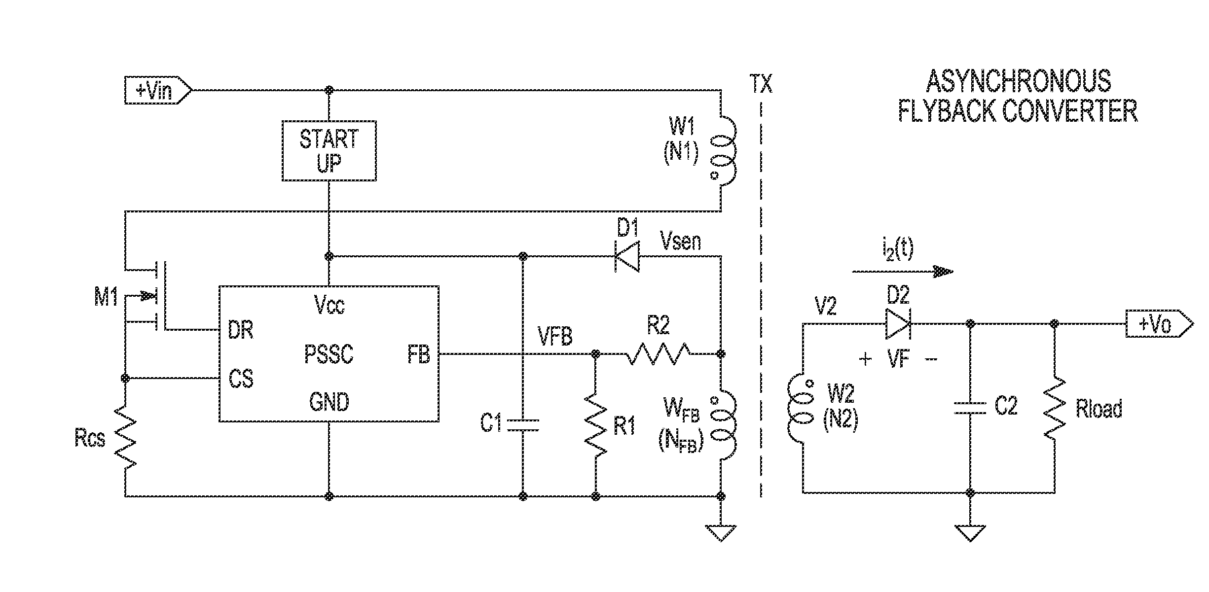
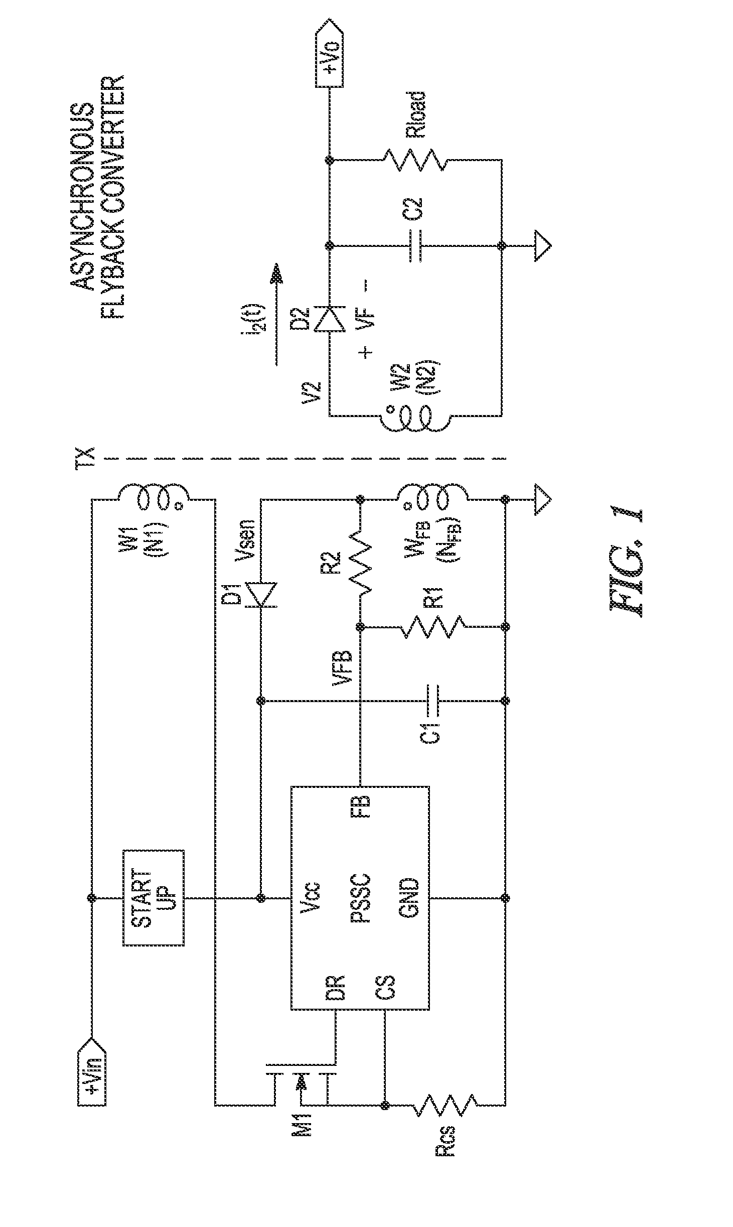
[0061]Generally, embodiments provide methods for soft turn off of a synchronous rectifier (SR) such as a field effect (e.g., MOSFET) SR, and a circuit implementing the method. The method may eliminate the sampling errors in Primary Side Sensing (PSS) controllers and / reduce EMI emitted from the SMPS; which may be caused by conventional hard driven synchronous rectifiers. Advantageously, an embodiment is utilised in a discontinuous, synchronous Flyback converter.

[0062]Embodiments deliver methods for driving a SR, preferably a MOSFET SR, in a way that is compatible with PSS used in Switched Mode Power Converters (SMPC), and circuit implementation of the said method. (Embodiments are applicable to DC-DC converters and AC-DC supplies, so that SMPC and SMPS (Switched Mode Power Supply) are used interchangeably herein).

[0063]The synchronous rectifier (SR) controller, or SR driver, may be a MOSFET driver specifically designed for use in a single switch Flyback converter operating in DCM. A ...


PUM


Abstract

This invention generally relates to synchronous rectifier controllers for an SMPS. One controller comprises: a sensor to sense a signal on a secondary side, to detect turn off of the switch; a charge source to, in response to a said detection, charge a control terminal of the rectifier to a voltage beyond a threshold voltage of the synchronous rectifier to allow the synchronous rectifier to conduct current of the secondary winding; and a linear amplifier having an output to sink current from the control terminal dependent on a difference between a voltage across the synchronous rectifier and an amplifier reference value, said voltage across the synchronous rectifier being a voltage across a controllable conduction path for current of the secondary winding, the linear amplifier to inhibit discharge of the control terminal from the voltage beyond the threshold voltage until the voltage across the synchronous rectifier reaches the amplifier reference value.

Description

FIELD OF THE INVENTION[0001]This invention generally relates to synchronous rectifier controllers for a switched mode power supply (SMPS) comprising a synchronous rectifier, SMPSs—in particular flyback switched mode power converters operating in discontinuous current mode and using primary side sensing—and methods for controlling a synchronous rectifier of an SMPS.BACKGROUND TO THE INVENTION[0002]In a switch mode power supply (SMPS), broadly speaking, a magnetic energy storage device such as a transformer or inductor is used to transfer power from an input side to an output side of the SMPS. A power switch switches power to the primary side of the energy storage device, during which period the current and magnetic field builds up linearly. When the switch is opened the magnetic field (and secondary side current) decreases substantially linearly as power is drawn by the load on the output side.[0003]An SMPS may operate in either a discontinuous conduction mode (DCM) or in continuous ...

Claims


Application Information

Patent Timeline
Patent Type & Authority Applications(United States)
IPC IPC(8): H02M3/335
CPCH02M3/33592H02M1/36H02M3/33523Y02B70/10
Inventor LEFEDJIEV, ADRIANWERNER, TOINE
Owner POWER INTEGRATIONS INC
Why Eureka
Try Eureka