Filtering choke arrangement

a filtering choke and choke technology, applied in the direction of transformers/inductance coils/windings/connections, cores/yokes, inductance, etc., can solve the problems of large space needs and cost needed for two separate chokes, weak ability to attenuate common-mode currents, and even greater space needs and costs

Active Publication Date: 2009-06-04
VACON OY
View PDF3 Cites 22 Cited by
  • Summary
  • Abstract
  • Description
  • Claims
  • Application Information

AI Technical Summary

Benefits of technology

[0014]The choke arrangement according to the invention is suited best to locations in which an active input bridge is connected in the direction of the supply network, e.g. PWM frequency converters provided with a so-called AFE bridge. The same type of choke can of course also be used on the output side of the frequency converter to attenuate the harmonics and common-mode currents supplied to the motor circuit. The arrangement is especially suited for filtering the switching frequency harmonics characteristic to a PWM frequency converter and for reducing the steepness of the rising edges and falling edges of voltage pulses (du / dt filtering).

Problems solved by technology

A drawback of the solution is the large space needs and cost needed for two separate chokes.
Using phase-specific chokes is also possible, but in this case the space needs and cost are even greater.
One weakness of the choke solution according to FIG. 3 is also that its ability to attenuate common-mode currents is weak.
Common-mode currents, i.e. currents that travel in a synchronous phase in all phases, cause most of the switching phenomena of the fast power semiconductor switches of the AFE and the INU, and they are known to be the main cause of the high-frequency interference caused in the environment of the device.

Method used


Image

  • Filtering choke arrangement
  • Filtering choke arrangement
  • Filtering choke arrangement

Examples


Embodiment Construction

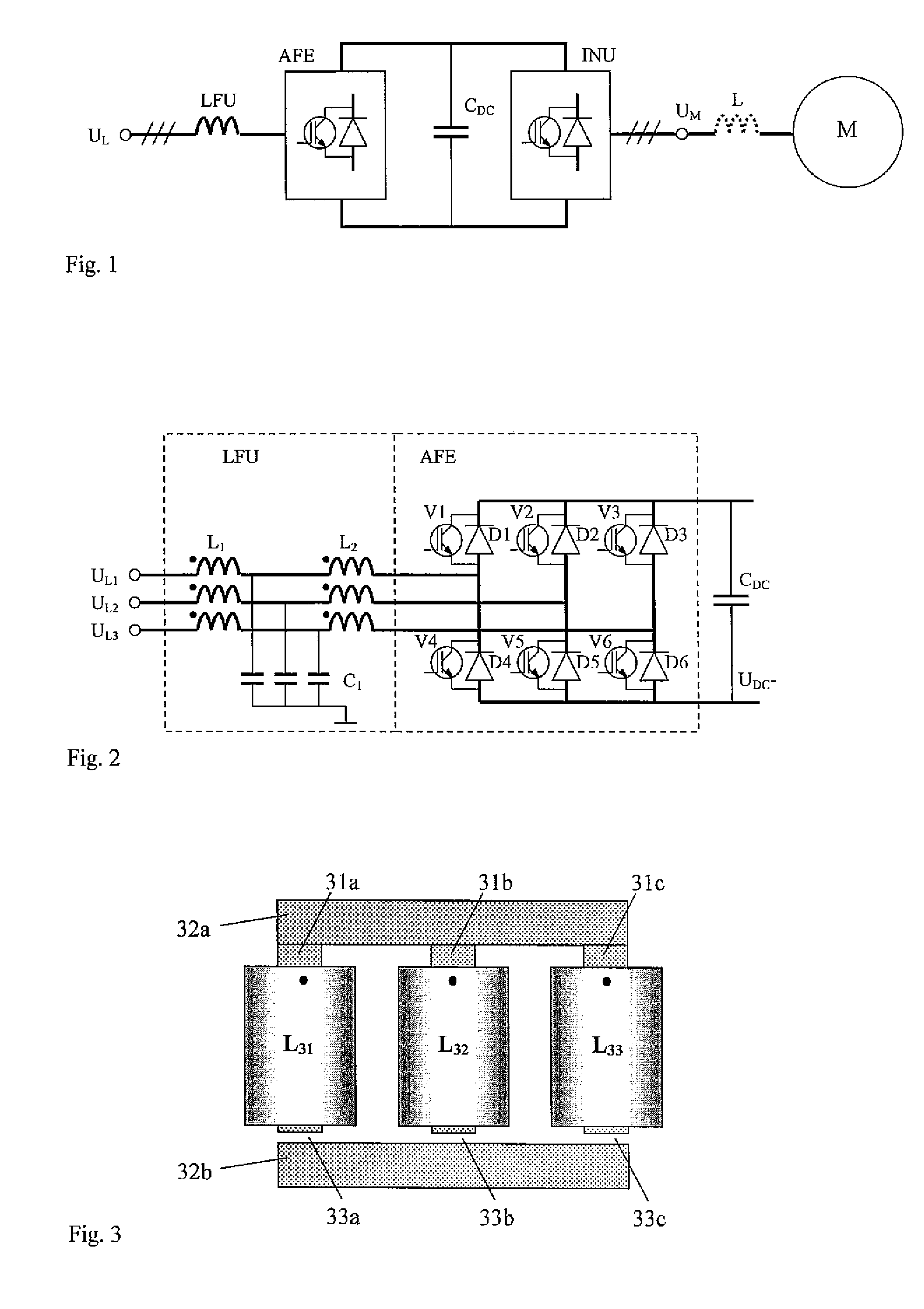
[0027]FIG. 1 contains a view on a block diagram level of a three-phase AC motor drive provided with regenerative braking regulation of the speed of rotation, which motor drive comprises a filter unit LFU, a network bridge AFE with regenerative braking, a filtering capacitor CDC of the DC voltage of the intermediate circuit of the frequency converter, an inverter INU, an output filter L that is necessary in some cases, and also a motor M. This invention relates to the filter unit LFU and more particularly to the choke it comprises. The same kind of choke can be used also as an output filter L, in which it brings advantages in, among other things, the attenuation of common-mode interference.

[0028]FIG. 2 presents a more detailed circuit diagram of the blocks LFU and AFE. The LFU unit comprises two three-phase chokes L1 and L2, which are wound e.g. in the direction presented in the figure with a dot marking known in the art. The filter unit LFU normally also comprises phase-specific cap...


PUM

PropertyMeasurementUnit
magneticaaaaaaaaaa
shapeaaaaaaaaaa
braking energyaaaaaaaaaa

Abstract

A polyphase filtering choke arrangement of a power electronics appliance, more particularly of a frequency converter. which arrangement comprises two separate magnetic cores, around both of which a polyphase winding is arranged, particularly for filtering the harmonics of a network current and the common-mode noise currents, wherein both the magnetic cores (1, 2, 101a-101c, 102a-102c, 130a-130d, 140a-140d) are shaped to form a closed magnetic circuit, the magnetic cores (1 and 2, 101a-101c and 102a-102c, 130a-130d and 140a-140d) are arranged one on top of the other, the magnetic cores are connected to each other with connecting pieces (11-13, 11a-13b, 111-113, 121-124), and the winding directions of the windings of the magnetic cores are opposing with respect to each other, in which case the fluxes produced in the magnetic cores of each current are of opposing directions, in which case the flux produced by the difference-mode current circulates via the connecting pieces from one magnetic core to another.

Description

FIELD OF TECHNOLOGY [0001]The object of this invention is a filtering choke arrangement of a power electronics appliance, more particularly of PWM frequency converter provided with an active network bridge. The choke arrangement is suited to filtering the harmonics of a three-phase network current and the common-mode noise currents, but it can be used also to limit the harmonics of a three-phase output current.PRIOR ART [0002]The use of an active network bridge in frequency converters, in which network bridge semiconductor switches are used, is known to be necessary when it is desired to lead the braking energy of the motor connected to the frequency converter back to the supply network. It is also known that the waveform of the network current produced by an active network bridge is almost sinusoidal. That being the case the harmonics content of it is low which is also a good reason to use an active network bridge e.g. in the kinds of cases in which the network current of the elect...

Claims


Application Information

Patent Timeline
Patent Type & Authority Applications(United States)
IPC IPC(8): H01F30/12
CPCH01F3/10H01F3/14H01F30/12H03H2001/0092H01F2017/0093H02M1/126H01F37/00H01F2003/106H02M1/123H01F27/263
Inventor SODO, NICKLAS
Owner VACON OY
Why Eureka
Try Eureka