Communication Device and Communication System
a communication device and communication system technology, applied in the field of communication devices and communication systems, can solve the problems of airplanes having constraints on space to be equipped with communication devices or wires, and achieve the effects of reducing the cost of communication, facilitating communication, and high-quality video transmission
- Summary
- Abstract
- Description
- Claims
- Application Information
AI Technical Summary
Benefits of technology
Problems solved by technology
Method used
Image
Examples
first embodiment
[0075]The following describes the first embodiment according to the present invention with reference to the drawings. Note that, in general, an unit to be transmitted via a network is called a frame for the Data link layer and an IP data gram for the Network layer, but in the description, the both units are referred to as a frame.
[0076]A data distribution system according to the present embodiment is used in an airplane 1 as shown in FIG. 4 as one example. In the data distribution system used in the airplane (hereinafter, referred to as an airplane program distribution system), as shown in FIG. 5, video programs and the like distributed from a video server 10 shown in FIG. 6 can be watched and listened by using a monitor 3 equipped on the back of each seat 2.
[0077]In general, airplanes have constraints on a space to be equipped with communication devices or wires. For example, as shown in FIG. 6, an area distribution box (ADB) 12 is equipped on a ceiling part of the airplane 1. A ma...
second embodiment
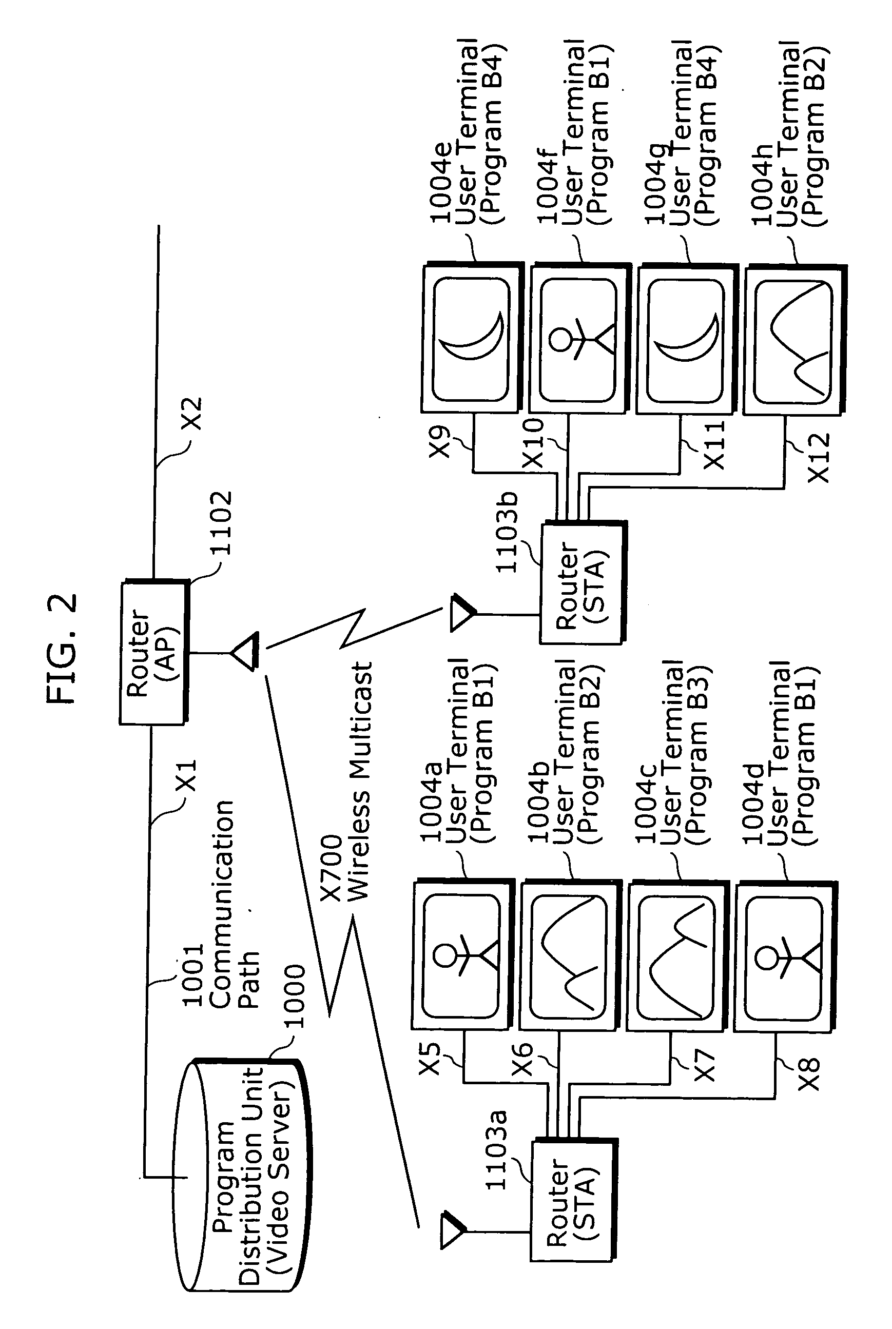
[0126]The second embodiment describes another example of the structure of the system which has been described with reference to FIG. 7. FIG. 12 is a diagram of a structure of the multicast communication according to the present application. In FIG. 12, a program distribution unit 100, the first communication path 101, and the first communication unit 102 are same as the respective units in FIG. 7. The system structure in FIG. 12 differs from the system structure in FIG. 7 in that a user terminal 605 has a function as a wireless station (STA). That is, the first communication unit (AP) 102a which is a wireless access point for wirelessly communicating directly with the user terminals 605a to 605h.
[0127]FIG. 13 is a diagram showing one example of processing according to the present invention. The following describes the second embodiment with reference to FIGS. 12 and 13. Note that the IGMP processing is assumed to have already been performed between the user terminal and the first c...
third embodiment
[0139]The third embodiment describes a method by which the IP Multicast frame is used directly at the Network layer, and the re-transmission processing is performed in the wireless communication, so that it is possible to realize high-quality transmission.
[0140]More specifically, in the wireless communication, by using a Multicast IP address directly in an IP address of a destination, and using a Unicast MAC address in a MAC address of a destination, the re-transmission processing can be performed.
[0141]The third embodiment can be applied to the first embodiment described with reference to FIG. 7 and the second embodiment described with reference to FIG. 12. Note that the IP address used in the third embodiment is the same as the IP address used in the first embodiment.
[0142]Firstly, as shown in the system structure of FIG. 7, since the user terminal 105a and the user terminal 105d request for the program A1 to be watched or listened to, the first communication unit 102a uses a Mult...
PUM
 Abstract
Description
Claims
Application Information
 - R&D
- Intellectual Property
- Life Sciences
- Materials
- Tech Scout
- Unparalleled Data Quality
- Higher Quality Content
- 60% Fewer Hallucinations
Browse by: Latest US Patents, China's latest patents, Technical Efficacy Thesaurus, Application Domain, Technology Topic, Popular Technical Reports.
© 2025 PatSnap. All rights reserved.Legal|Privacy policy|Modern Slavery Act Transparency Statement|Sitemap|About US| Contact US: help@patsnap.com


