Optical transmission system

a transmission system and optical technology, applied in the field of optical transmission systems, can solve the problems of difficult uniform maintenance of the conventional cwdm optical transmission system, and achieve the effects of high efficiency, high efficiency, and positive chromatic dispersion

Inactive Publication Date: 2008-02-12
SUMITOMO ELECTRIC IND LTD
View PDF32 Cites 1 Cited by
  • Summary
  • Abstract
  • Description
  • Claims
  • Application Information

AI Technical Summary

Benefits of technology

[0011]In the optical transmission system according to the present invention, of the optical fiber transmission line, at least a transmission line section which functions as the optical fiber for Raman amplification preferably includes an optical fiber with a negative chromatic dispersion in a wavelength band containing the signal light. Generally, an optical fiber transmission line has positive chromatic dispersion. The chromatic dispersion is compensated for by the optical fiber included in the SRS means, and high-quality signal transmission can be performed.
[0012]In the optical transmission system according to the present invention, of the optical fiber transmission line, at least a transmission line section which functions as the optical fiber for Raman amplification may include an optical fiber with a loss peak of 0.33 dB / km or less due to OH-radicals near a wavelength of 1.39 μm. In this case, since pumping light near the wavelength of 1.39 μm can be supplied at a high efficiency, the pumping efficiency can be increased, and the gain spectrum can also be improved.
[0014]In the optical transmission system according to the present invention, the SRS means preferably Raman-amplifies, of the plurality of signal channels contained in the signal light, a signal channel in a wavelength range where a transmission loss in the optical fiber transmission line is a first threshold value or more. The SRS means preferably further comprises a dispersion compensation means which compensates for a chromatic dispersion of a signal channel, of the plurality of signal channels contained in the signal light, in a wavelength range where an accumulated chromatic dispersion in the optical fiber transmission line is a second threshold value or more. In either case, since Raman amplification or dispersion compensation can be executed in a necessary wavelength range in the signal wavelength band, high-quality signal transmission of each signal channel can be performed.
[0016]In the optical transmission system according to the present invention, as a CWDM optical transmission system, Raman amplification in a wider wavelength band can be performed while maintaining the number of light sources small.
[0018]In particular, in the optical transmission system according to the present invention, an optical frequency of each pumping channel contained in the pumping light is so set as to locate a peak of Raman gain at an optical frequency different from an optical frequency of each signal channel contained in the signal light. More specifically, the optical frequency of the signal channel is lower than that of the pumping channel by 13.2 THz. More specifically, the optical frequency of each pumping channel contained in the pumping light is preferably so set as to locate the peak of Raman gain at an optical frequency separated from the optical frequency of each signal channel contained in the signal light by 624 GHz (5 nm). On the other hand, the optical frequency of each pumping channel contained in the pumping light is preferably so set as to locate the peak of Raman gain at an optical frequency not separated from the optical frequency of each signal channel contained in the signal light by 1,248 GHz (10 nm) or more. Accordingly, in the CWDM optical transmission system, a high gain flatness can be obtained in a wider wavelength band while keeping the number of pumping light sources small.

Problems solved by technology

Hence, it is difficult for the conventional CWDM optical transmission system to uniformly maintain the transmission quality of each signal channel contained in the signal wavelength band.

Method used


Image

  • Optical transmission system
  • Optical transmission system
  • Optical transmission system

Examples


first embodiment

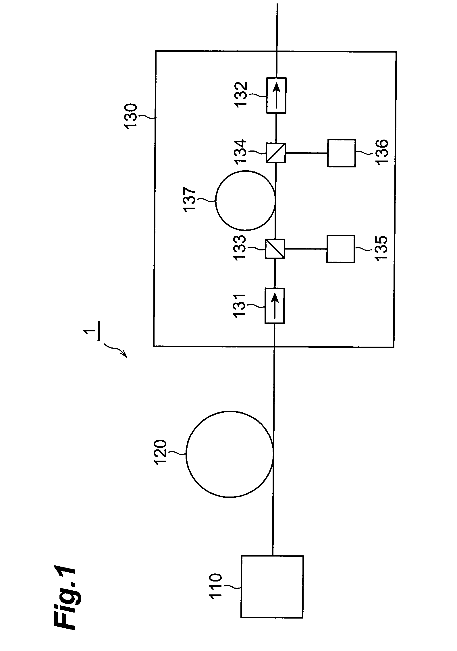
[0052]An optical transmission system according to a first embodiment of the present invention will be described first. FIG. 1 is a view showing the arrangement of an optical transmission system according to the first embodiment of the present invention. An optical transmission system 1 shown in FIG. 1 is a CWDM optical transmission system comprises at least an optical transmitter 110, optical fiber transmission line 120, and lumped Raman amplifier (LRA) 130.

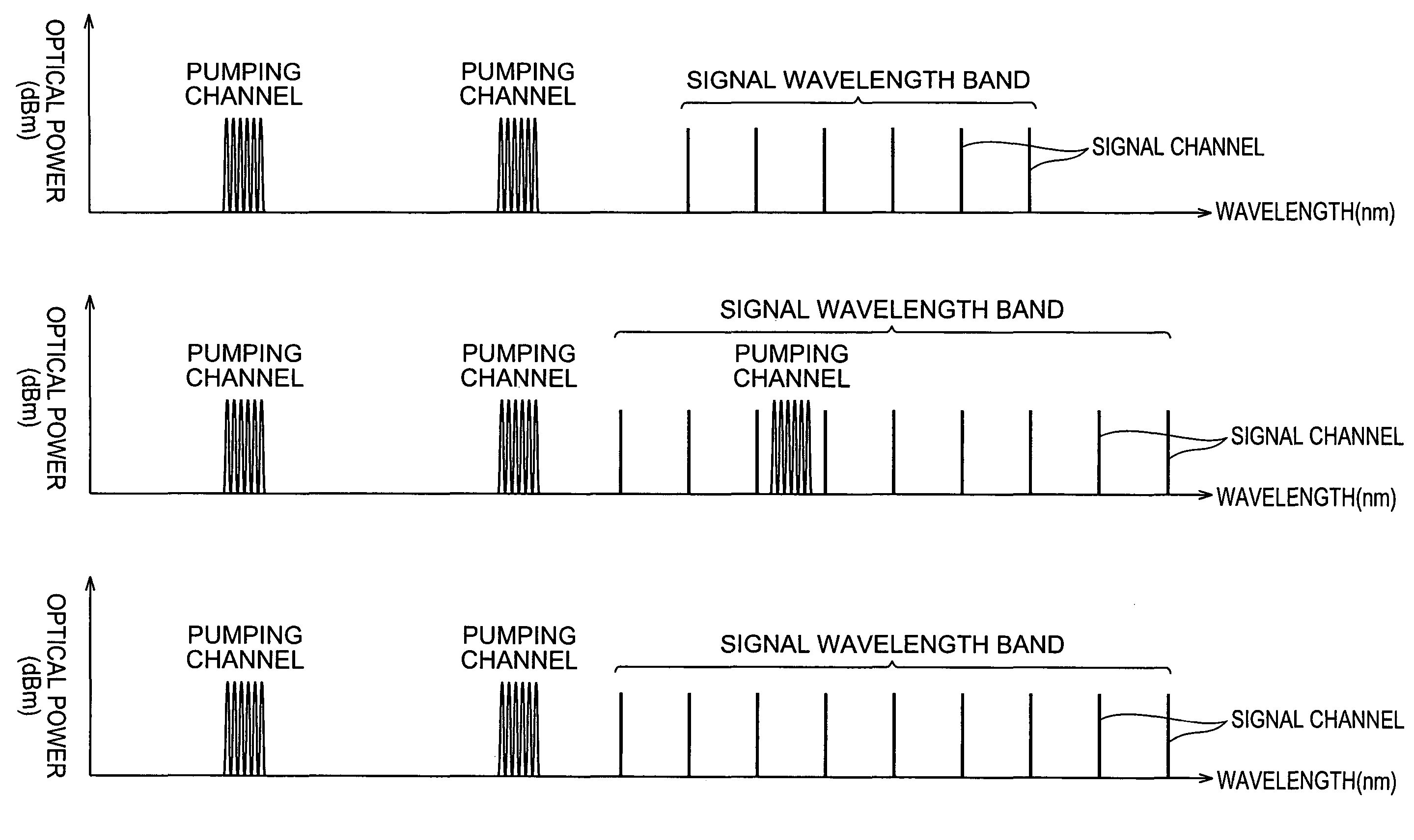
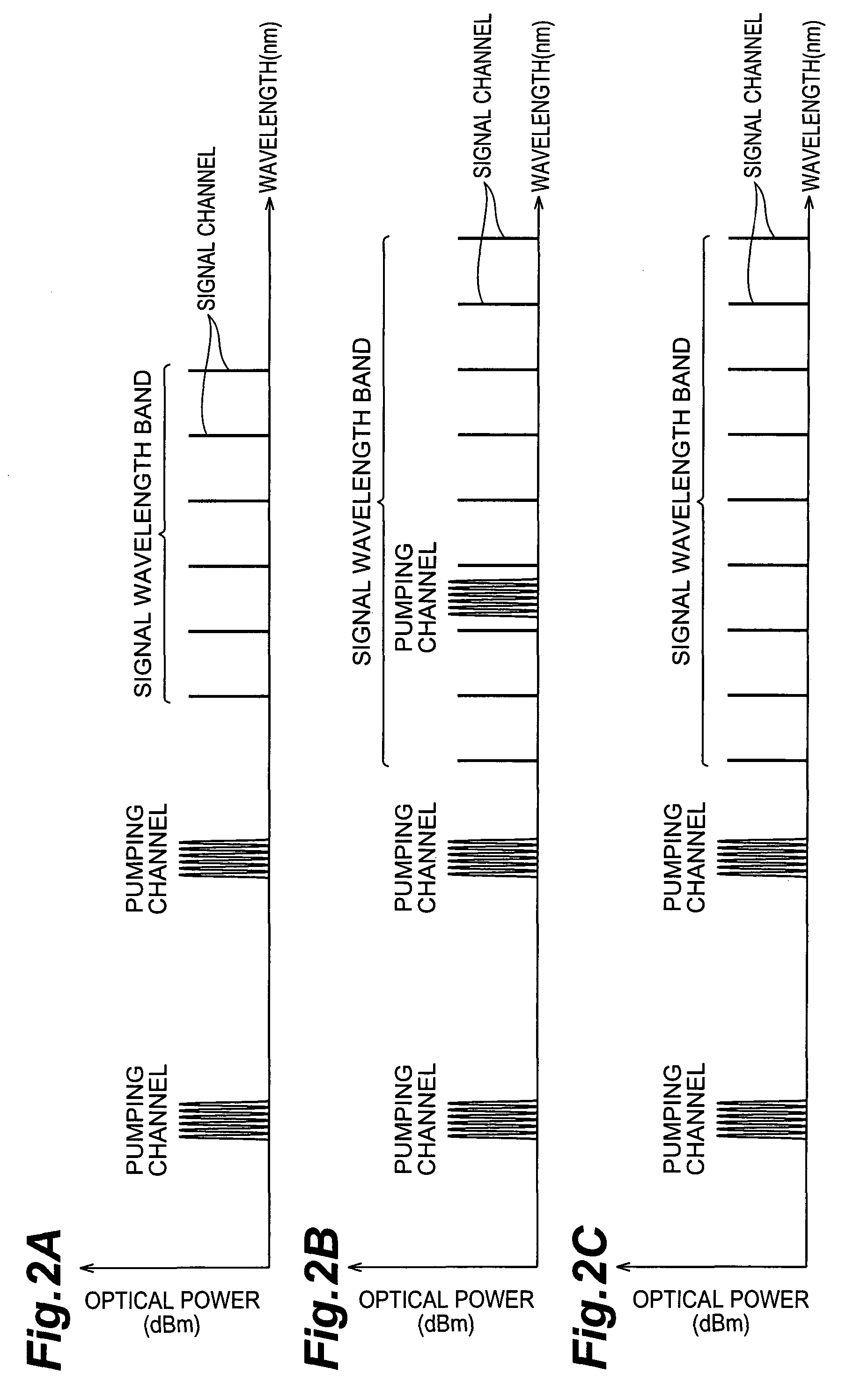
[0053]The optical transmitter 110 outputs signal light (WDM signal) in which a plurality of signal channels with an optical frequency spacing of 400 GHz or more but to 12.5 THz or less are multiplexed. The wavelength spacing (channel spacing) of the multiplexed signal light outputted from the optical transmitter 110 is preferably 10 nm or more. As a light source that outputs each signal channel, for example, a distributed feedback laser light source, Fabry-Perot semiconductor laser light source (FP-LD), or a fiber grating laser l...

second embodiment

[0064]An optical transmission system according to a second embodiment of the present invention will be described next. FIG. 3 is a view showing the arrangement of an optical transmission system according to the second embodiment of the present invention. An optical transmission system 2 shown in FIG. 3 is a CWDM optical transmission system comprises an optical transmitter 110, optical fiber transmission line 120, and lumped Raman amplifier 230. The optical transmission system 2 according to the second embodiment is different from the optical transmission system 1 according to the first embodiment described above in the Raman amplifier 230 is arranged in place of the Raman amplifier 130.

[0065]The Raman amplifier 230 according to the second embodiment has, sequentially from the signal light input end to the signal light output end, an optical fiber for Raman amplification 137 (the optical fiber for Raman amplification 137 constitutes part of the optical fiber transmission line arrange...

third embodiment

[0068]An optical transmission system according to a third embodiment of the present invention will be described next. FIG. 4 is a view showing the arrangement of an optical transmission system according to the third embodiment of the present invention. An optical transmission system 3 shown in FIG. 4 is a CWDM optical transmission system comprises an optical transmitter 110, optical fiber transmission line 120, optical receiver 140, optical isolators 131 and 132, optical couplers 133 and 134, and pumping light source units 135 and 136. The optical fiber transmission line 120 is connected between the optical transmitter 110 and the optical receiver 140. The optical isolator 131, optical coupler 133, and pumping light source unit 135 are arranged on the side of the optical transmitter 110 of the optical fiber transmission line 120. The optical isolator 132, optical coupler 134, and pumping light source unit 136 are arranged on the side of the optical receiver 140 of the optical fiber ...


PUM

PropertyMeasurementUnit
optical frequencyaaaaaaaaaa
wavelength spacingaaaaaaaaaa
wavelengthaaaaaaaaaa

Abstract

This invention provides an optical transmission system which allows to perform high-quality transmission of each of a plurality of signal channels multiplexed. In the optical transmission system, signal light in which a plurality of signal channels with an optical frequency spacing of 400 GHz or more but 12.5 THz or less is transmitted from an optical transmitter to a Raman amplifier through an optical fiber transmission line. In the Raman amplifier, pumping light from a pumping light source unit is supplied to an optical fiber through an optical coupler. The multiplexed signal light inputted to the Raman amplifier arrives at the optical fiber through an optical isolator and optical coupler, and Raman-amplified by the optical fiber. The Raman-amplified multiplexed signal light is outputted from the Raman amplifier through an optical coupler and optical isolator.

Description

CROSS-REFERENCE TO RELATED APPLICATION[0001]This application claims priority to Provisional Application Serial No. 60 / 452,492 filed on Mar. 7, 2003, which is hereby incorporated by reference in its entirety.BACKGROUND OF THE INVENTION[0002]1. Field of the Invention[0003]The present invention relates to an optical transmission system which transmits signal light in which a plurality of signal channels with optical frequencies different from each other are multiplexed.[0004]2. Related Background Art[0005]A wavelength division multiplexing (WDM) optical transmission system is an optical system which transmits, through an optical fiber transmission line, signal light (WDM signal light) in which a plurality of signal channels with optical frequencies different from each other are multiplexed. The WDM optical transmission system can transmit / receive a large quantity of information at a high speed. For the optical transmission system as a backbone network with a great demand for communicat...

Claims


Application Information

Patent Timeline
Patent Type & Authority Patents(United States)
IPC IPC(8): H01S3/00G02F1/35H01S3/10H01S3/30H04B10/2525H04B10/29H04B10/291H04J14/00H04J14/02
CPCH04B10/2525H04B10/2916H04B2210/003
Inventor MIYAMOTO, TOSHIYUKISHIGEMATSU, MASAYUKINISHIMURA, MASAYUKI
Owner SUMITOMO ELECTRIC IND LTD
Why Eureka
Try Eureka