Optical transmission system

a transmission system and optical transmission technology, applied in the field of optical transmission systems, can solve the problems of difficult uniform maintenance of the conventional cwdm optical transmission system and the inability to achieve flatness. to be easily increased, and achieve the effect of uniform maintenance and improved flatness

Inactive Publication Date: 2004-02-12
SUMITOMO ELECTRIC IND LTD
View PDF24 Cites 5 Cited by
  • Summary
  • Abstract
  • Description
  • Claims
  • Application Information

AI Technical Summary

Problems solved by technology

Hence, it is difficult for the conventional CWDM optical transmission system to uniformly maintain the transmission quality of each signal channel contained in the signal wavelength band.
However, in the conventional CWDM optical transmission system, however, since the channel spacing of pumping light is 6 nm or more but 35 nm or less, the gain flatness can hardly be further increased while keeping the number of pumping LDs small.

Method used


Image

  • Optical transmission system
  • Optical transmission system
  • Optical transmission system

Examples


Embodiment Construction

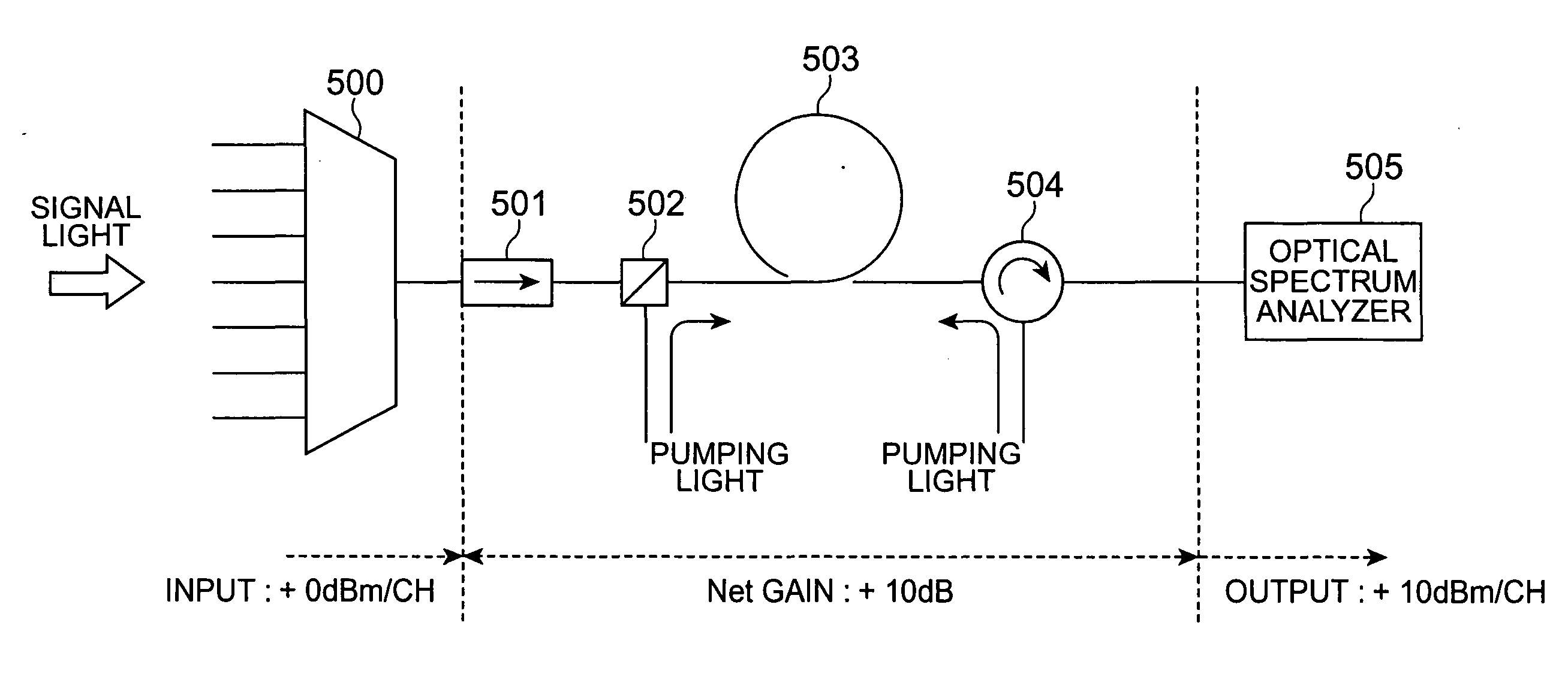
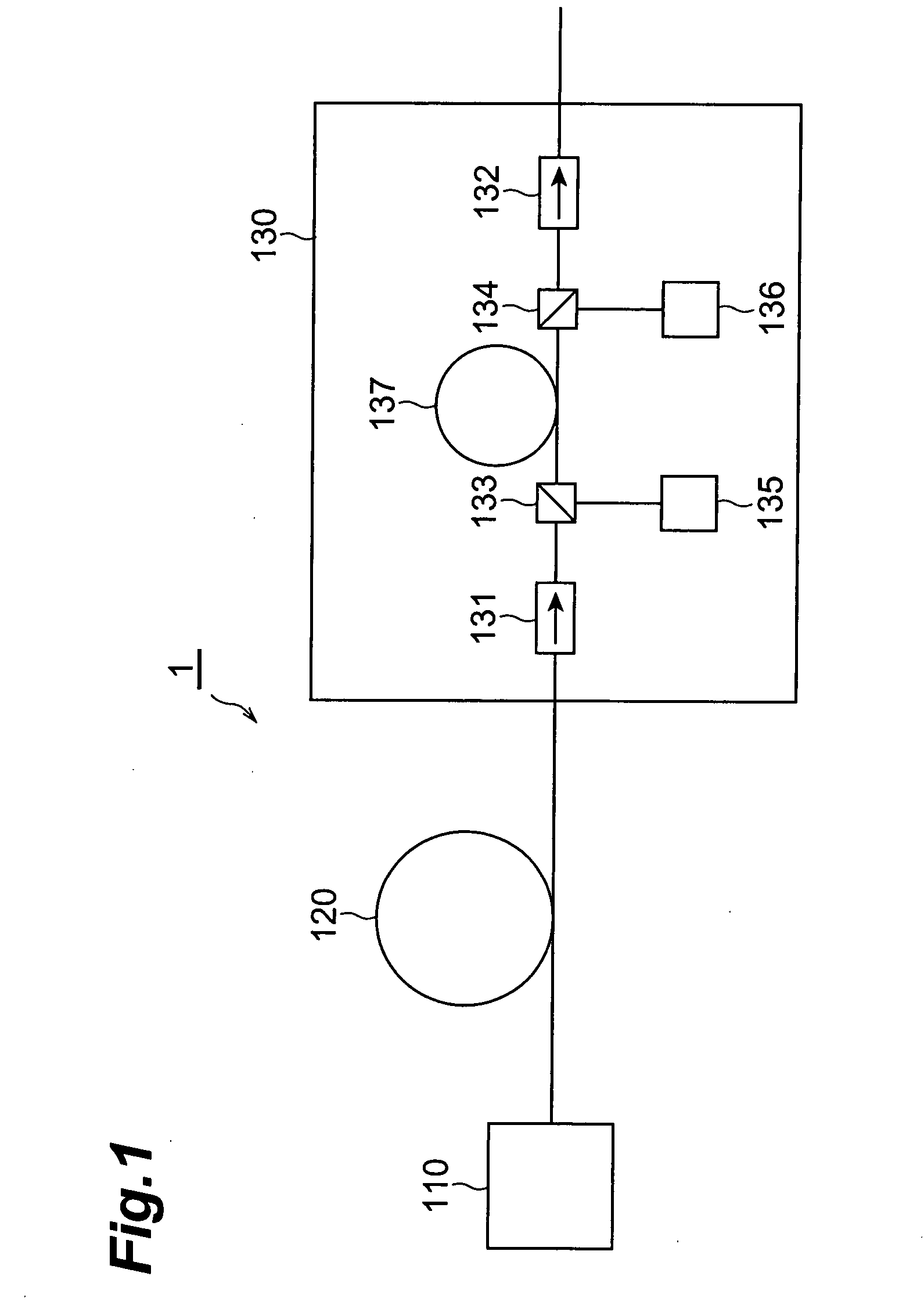
[0087] A detailed example of the optical transmission system 3 according to the third embodiment will be described next. The optical fiber transmission line 120 was 80 km long and was constituted by one of a standard single-mode optical fiber (SMF), dispersion-shifted optical fiber (DSF), and non-zero dispersion-shifted optical fiber (NZDSF). Multiplexed signal light outputted from the optical transmitter 110 contained six channels with a spacing of 20 nm in a wavelength band of 1,510 to 1,610 nm. The wavelength and power of pumping light to be outputted from the pumping light source units 135 and 136 were set such that the net gain G.sub.net of Raman amplification in the optical fiber transmission line 120 became -17 dB. The number of pumping channels were 2 or 3. When the number of pumping channels was 2, the wavelengths of the pumping channels were 1,420 nm and 1,490 nm. When the number of pumping channels was 3, the wavelengths of the pumping channels were 1,420 nm, 1,460 nm, an...


PUM

PropertyMeasurementUnit
optical frequency spacingaaaaaaaaaa
wavelengthaaaaaaaaaa
optical frequencyaaaaaaaaaa

Abstract

This invention provides an optical transmission system which allows to perform high-quality transmission of each of a plurality of signal channels multiplexed. In the optical transmission system, signal light in which a plurality of signal channels with an optical frequency spacing of 400 GHz or more but 12.5 THz or less is transmitted from an optical transmitter to a Raman amplifier through an optical fiber transmission line. In the Raman amplifier, pumping light from a pumping light source unit is supplied to an optical fiber through an optical coupler. The multiplexed signal light inputted to the Raman amplifier arrives at the optical fiber through an optical isolator and optical coupler, and Raman-amplified by the optical fiber. The Raman-amplified multiplexed signal light is outputted from the Raman amplifier through an optical coupler and optical isolator.

Description

[0001] This application claims priority to Provisional Application Serial No. 60 / 452,492 filed on Mar. 7, 2003, which is hereby incorporated by reference in its entirety.[0002] 1. Field of the Invention[0003] The present invention relates to an optical transmission system which transmits signal light in which a plurality of signal channels with optical frequencies different from each other are multiplexed.[0004] 2. Related Background Art[0005] A wavelength division multiplexing (WDM) optical transmission system is an optical system which transmits, through an optical fiber transmission line, signal light (WDM signal light) in which a plurality of signal channels with optical frequencies different from each other are multiplexed. The WDM optical transmission system can transmit / receive a large quantity of information at a high speed. For the optical transmission system as a backbone network with a great demand for communication, a further increase in capacity has been examined by red...

Claims


Application Information

Patent Timeline
Patent Type & Authority Applications(United States)
IPC IPC(8): G02F1/35H01S3/10H01S3/30H04B10/2525H04B10/29H04B10/291H04J14/00H04J14/02
CPCH04B10/2525H04B2210/003H04B10/2916
Inventor MIYAMOTO, TOSHIYUKISHIGEMATSU, MASAYUKINISHIMURA, MASAYUKI
Owner SUMITOMO ELECTRIC IND LTD
Why Eureka
Try Eureka