Time domain digital temperature sensing system and method thereof

Inactive Publication Date: 2009-06-04
NAT TAIWAN UNIV OF SCI & TECH
View PDF15 Cites 28 Cited by
  • Summary
  • Abstract
  • Description
  • Claims
  • Application Information

AI Technical Summary

Benefits of technology

[0008]The present invention also provides a digital temperature sensing method for converting a test temperature into a digital output signal. The digital temperature sensing method comprises the steps of: generating a thermally sensitive time signal of which a width varies with the test temperature; generating a time reference signal of which a width changes with a digital set value; generating a time comparison signal according to a width difference between the thermally sensitive time signal and the time reference signal; determining whether the width of the thermally sensitive time signal and the width of time reference signal are close enough or substantially equal; and adjusting the digital set value according to the time comparison signal. Conventional temperature sensing system is operated in the voltage-domain. For a fixed operation voltage, to obtain a high resolution, a small unit voltage VLSB corresponding to the least significant bit of the digital set value is required. Due to the limitation imposed by input offset voltage of the subsequent voltage comparator, the difficulty for voltage discrimination increases as the unit voltage VLSB becomes small, and the measurement error increases also. Unlike the conventional systems, the digital temperature sensing system in accordance with the present invent

Problems solved by technology

Due to the limitation imposed by input offset voltage of the subsequent voltage comparator, the difficulty for voltage discrimination increases as the unit voltage VLSB becomes small, and the measurement error increases also.
As a result, the measurement error

Method used


Image

  • Time domain digital temperature sensing system and method thereof
  • Time domain digital temperature sensing system and method thereof
  • Time domain digital temperature sensing system and method thereof

Examples


Embodiment Construction

[0034]The present invention will now be described more specifically with reference to the following embodiments. It is noted that the following description of the preferred embodiments of the present invention are presented herein for purpose of illustration and description only, and it is not intended to be exhaustive or to be limited to the precise form disclosed.

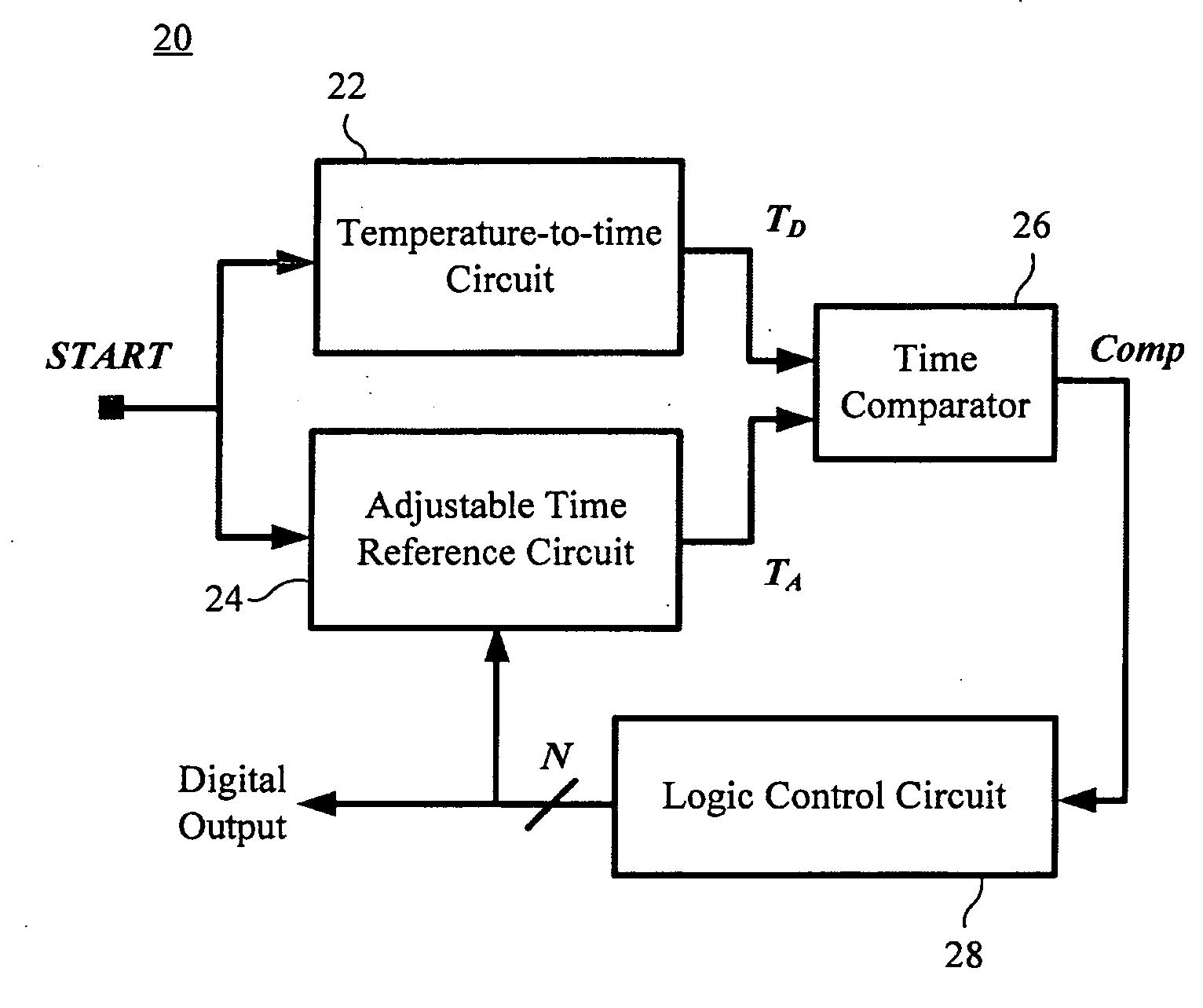
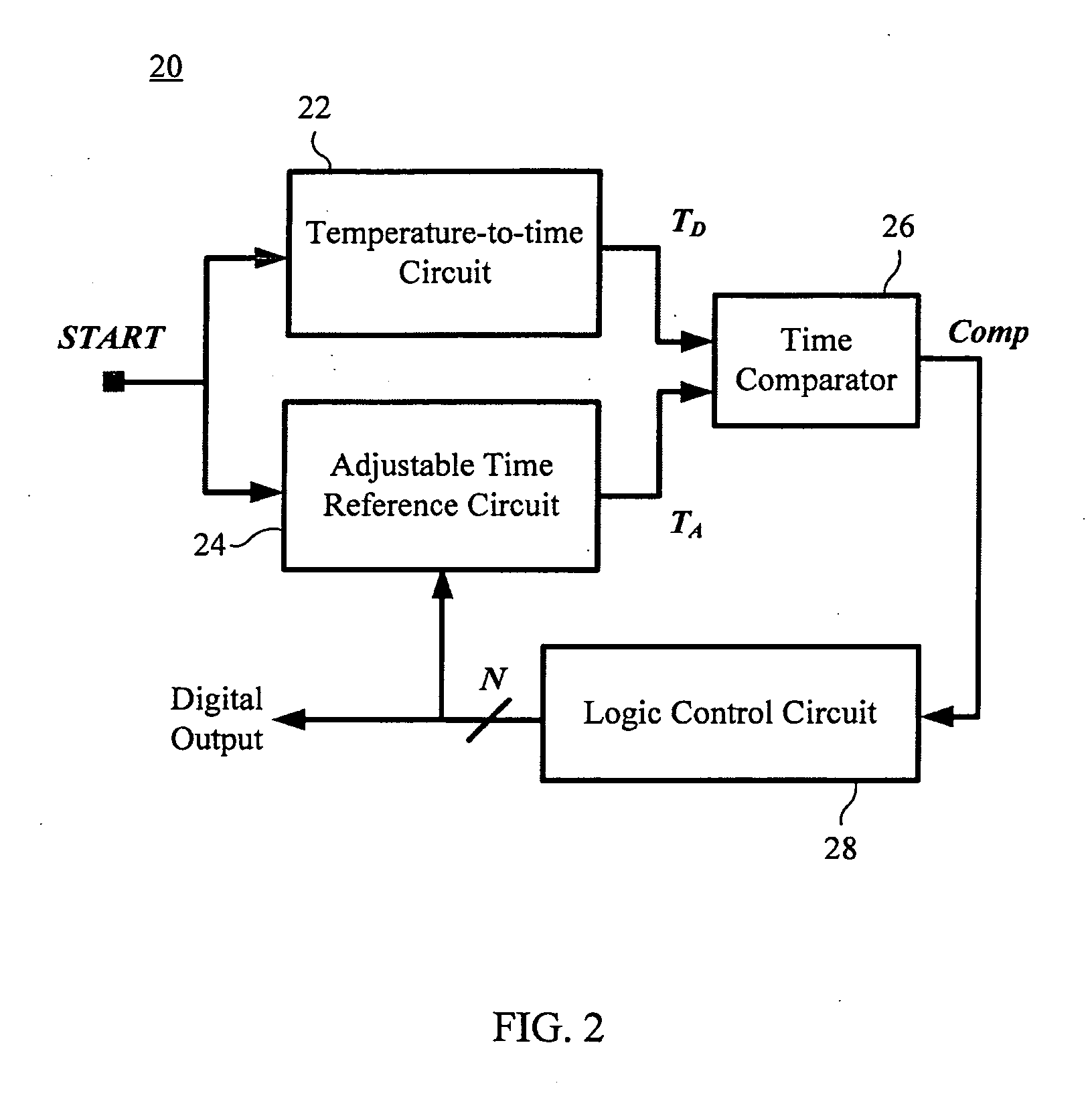
[0035]The present invention relates to a digital temperature sensing system, as well as a method, that converts a “test temperature” into a digital output signal. It is noted that the term “test temperature” used herein simply refers to, for example, an external temperature of the environment in which the digital temperature sensing system of the present invention is positioned. The digital temperature sensing system, broadly designated at 20, in accordance with a preferred embodiment of the present invention is illustrated in FIG. 2. The digital temperature sensing system 20 comprises a temperature-to-time circuit 22, an...


PUM


Abstract

A digital temperature sensing system and method for converting a test temperature into a digital output signal are disclosed. The system comprises a temperature-to-time circuit for generating a thermally sensitive time signal of which a width varies with the test temperature; an adjustable time reference circuit for generating a time reference signal of which a width changes with the digital set value; a time comparator for generating a time comparison signal according to a width difference between the thermally sensitive time signal and the time reference signal; a logic control circuit for adjusting the digital set value of the adjustable time reference circuit according to the time comparison signal so that the width of the thermally sensitive time signal and the width of time reference signal are close enough or substantially equal.

Description

[0001]This application claims the priority of Taiwan Patent Application No. 096146142, filed on Dec. 4, 2007. This invention is partly disclosed in a published article, Chun-Chi Chen, Poki Chen, and Kai-Ming Wang, “A SAR-Based Smart Temperature Sensor with Binary-Weighted Search Algorithm,” 18th VLSI Design / CAD Symposium, C3-3, Taiwan, 7-10 Aug. 2007.TECHNICAL FIELD OF THE INVENTION[0002]The present invention relates to a digital temperature sensing system and a method thereof. Particularly, the present invention relates to a digital temperature sensing system that is applicable to a central processing unit (CPU), a chipset, a battery protection circuit, an environmental monitoring system, an electromechanical system, or other circuits and systems that need temperature sensing circuits.BACKGROUND OF THE INVENTION[0003]Various techniques for digital temperature sensing are heretofore known. Some of these techniques rely on thermal resistors to measure a temperature. The measured temp...

Claims


Application Information

Patent Timeline
IPC IPC(8): G01K7/00
CPCG01K7/00G01K2219/00G01K7/346
Inventor CHEN, POKICHEN, CHUN-CHICHEN, TUO-KUANG
Owner NAT TAIWAN UNIV OF SCI & TECH
Why Eureka
Try Eureka