
Method for detecting a signal on a passive optical network

Active Publication Date: 2009-06-04
OPLINK COMM
View PDF20 Cites 1 Cited by
  • Summary
  • Abstract
  • Description
  • Claims
  • Application Information

AI Technical Summary

Benefits of technology

[0008]In this regard, the present invention provides for an improved transceiver assembly for use in an optical telecommunications network. The circuitry arrangement in the transceiver of the present invention generates a ranging signal that is transmitted along the fibers attached thereto and then filters the return signal in an manner that eliminates virtually all of the noise effects found on the fiber to provide a highly reliable timing signal for an accurate delay calculation. Further, the particular arrangement of the transceiver assembly of the present invention allows only a ranging signal that returns at the fundamental frequency to pass through the signal detect circuitry thereby insuring an accurate signal detect is being passed along for use in processing the delay signal for signal bursts transmitted along that fiber.
[0011]It is therefore an object of the present invention to provide a transceiver assembly that can be used in a passive optical networking environment that reduces the signal noise that is passed along to the signal detect monitor in order to reduce the number of false signal detect triggers. Further, it is an object of the present invention to provide a transceiver that filters the ranging signal in a manner that only allows the returning ranging signal to reach the detector to generate a signal detect signal thereby eliminating false triggers and insuring correct delay factor calculation.

Problems solved by technology

In other words, a plurality of subscribers utilizes one optical line in a time division multiplex manner, but a receiver on the line recognizes that each subscriber sends data in bursts at random times. The difficulty with this arrangement in a passive optical network is that received data or packets are different in both amplitude and phase from one another due to the differences in optical losses occurring on different transfer paths.
The difficulty arises as a result of the fact that, since optical signals degrade within a fiber optic cable over distance and pick up slight timing delays due to the distance traversed, the signal received 12 at the CO 6 from the closer service location has a timing delay and an amplitude that is larger than the amplitude of the signal received 10 at the CO 6 from the more distant location.
These differences in amplitude and timing become a problem because the passive optical network systems are time division multiuplexed (TDM) systems, where the CO 6 receiver is constantly receiving timed bursts 8, 10, 12 in a random pattern from each of the different locations, one after another, with a signal spacing of tens of nano-seconds.
Generally however the problem that is encountered in this mode is that the signal detect is often triggered prematurely by noise that is present in the system.
When noise is encountered during the time that the transceiver is waiting for the return signal, the transimpedance amplifier and or the post amplifier may treat noise detected in the system as a valid data signal thereby creating an incorrect delay factor.

Method used


Image

  • Method for detecting a signal on a passive optical network
  • Method for detecting a signal on a passive optical network
  • Method for detecting a signal on a passive optical network

Examples


Embodiment Construction

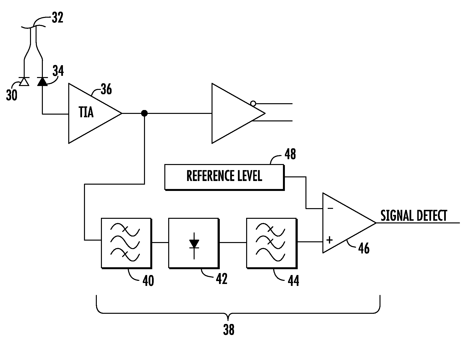
[0019]Now referring to the drawings, the arrangement for the transceiver assembly of the present invention is shown and generally illustrated in FIGS. 4 and 5. As was stated above the circuitry arrangement in the transceiver of the present invention generates a ranging signal that is transmitted along the fibers attached thereto and then filters the return signal in an manner that eliminates virtually all of the noise effects found on the fiber to provide a highly reliable timing signal for an accurate delay calculation. Further, the particular arrangement of the transceiver assembly of the present invention allows only a ranging signal that returns at the fundamental frequency to pass through the signal detect circuitry thereby insuring an accurate signal detect is being passed along for use in processing the delay signal for signal bursts transmitted along that fiber.

[0020]In the most general terms, the present invention as depicted in FIG. 4 is directed to a burst mode transceive...


PUM


Abstract

A transceiver assembly is provided for use in an optical telecommunications network. The circuitry arrangement in the transceiver of the present invention generates a ranging signal that is transmitted along the fibers attached thereto and then filters the return signal in an manner that eliminates virtually all of the noise effects found on the fiber to provide a highly reliable timing signal for an accurate delay calculation. A band pass filter is supplied in line before the input signal is allowed to pass to the ranging signal detector and comparator thereby allowing only a signal at the fundamental frequency of the input signal to pass, thereby eliminating false signal detect triggers.

Description

CROSS-REFERENCE TO RELATED APPLICATIONS[0001]This application is related to and claims priority from earlier filed U.S. Provisional Patent Application No. 60 / 990,991, filed Nov. 29, 2007.BACKGROUND OF THE INVENTION[0002]The present invention relates generally to fiber optic telecommunication systems. More specifically, the present invention relates to a fiber optic receiver assembly for use in a passive optical network that must receive, convert and sequence burst mode optical signals from a plurality of sources, wherein each signal being received has a different amplitude (power level) and relative timing as compared to adjacent bursts.[0003]In an effort to increase the available bandwidth for the delivery of services such as streaming media and the like, telecommunication companies are slowly starting to convert their carrier networks from traditional copper wiring to passive optical network systems as part of Fiber To The Premise (FTTP) and Fiber To The Home (FTTH) communication ...

Claims


Application Information

Patent Timeline
IPC IPC(8): H04B10/00
CPCH04B10/40H04B10/0773
Inventor MIREMADI, REZA
Owner OPLINK COMM
Features
  • Generate Ideas
  • Intellectual Property
  • Life Sciences
  • Materials
  • Tech Scout
  • Unparalleled Data Quality
  • Higher Quality Content
  • 60% Fewer Hallucinations
Learn More