Wind turbine metrology system

a technology for wind turbines and metrology systems, applied in the direction of rotors, vessel parts, instruments, etc., can solve the problems of turbines not optimally aligned with the oncoming wind, blades affecting the wind speed and direction, and less than optimum energy production

Inactive Publication Date: 2009-06-04
GENERAL ELECTRIC CO
View PDF5 Cites 33 Cited by
  • Summary
  • Abstract
  • Description
  • Claims
  • Application Information

AI Technical Summary

Problems solved by technology

The disadvantage to having the wind measuring devices mounted downwind and behind the blades / rotor, is that the blades affect the wind speed and direction.
These rotor induced fluid phenomena produce a systematic error in a nacelle mounted wind vane (typical on commercial wind turbines) such that the turbine is not optimally aligned with the oncoming wind.
The result can be less than optimum energy production, less than optimum startup operation, storm shutdown operation, and increases in mechanical stress.
The same fluid phenomena effects that disturb the wind vane sensor can also effect the wind speed anemometer such that it produces erroneous signals that in turn cause significant errors in the assessment of wind turbine performance.
However, there is typically a time lag between the occurrence of a gust and the actual pitching of the blades based upon dynamics of the pitch control actuator and the inertia of the mechanical components.
As a result, generator speed, and hence power, may increase considerably during such gusts, and may exceed the maximum prescribed power output level (also known as overspeed limit) causing the generator to trip, and in certain cases, the wind turbine to shut down.
Moreover, sudden gusts may also significantly increase tower fore-aft and side-to-side bending moments due to increase in the effect of wind shear.

Method used


Image

  • Wind turbine metrology system
  • Wind turbine metrology system
  • Wind turbine metrology system

Examples


Embodiment Construction

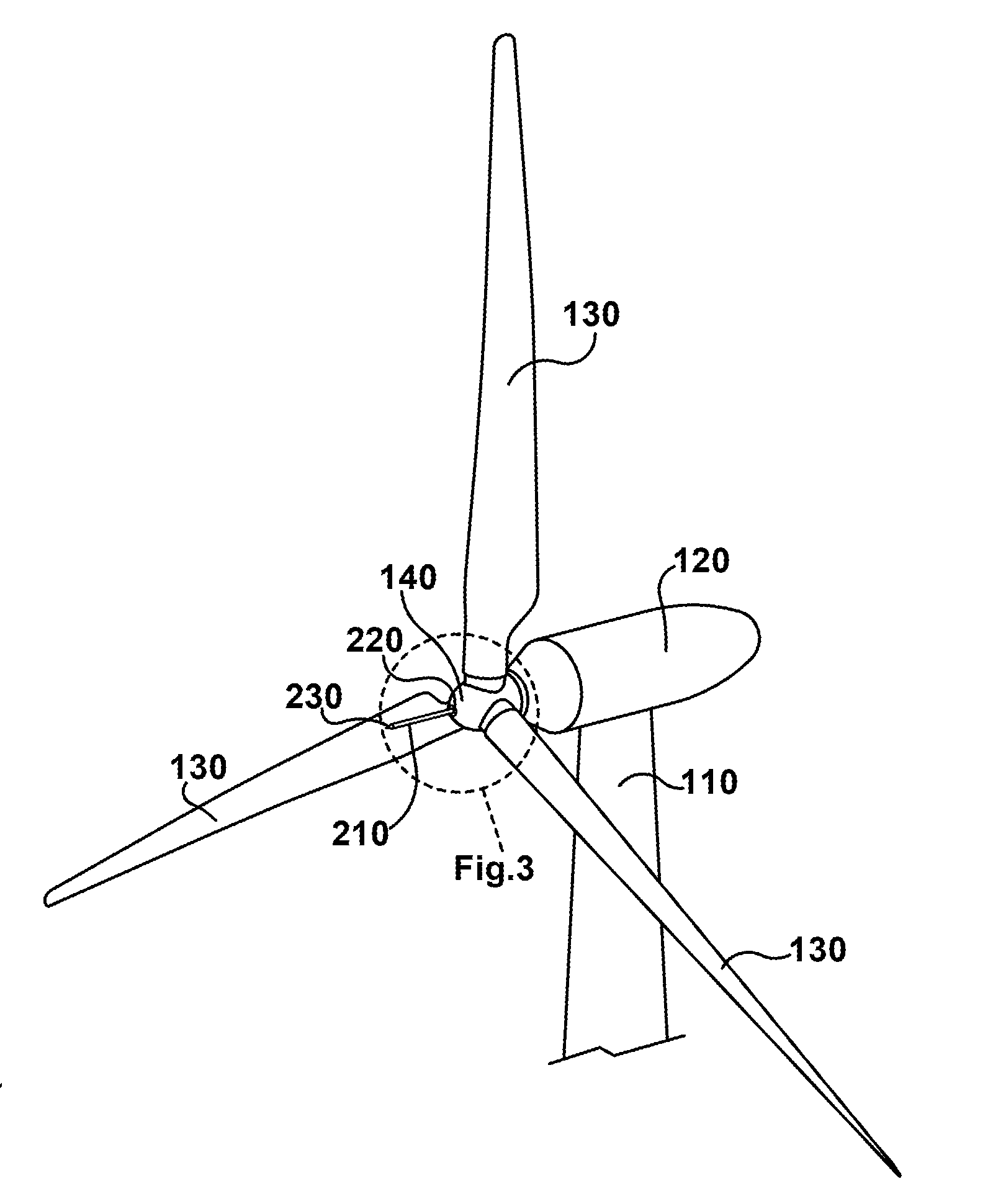
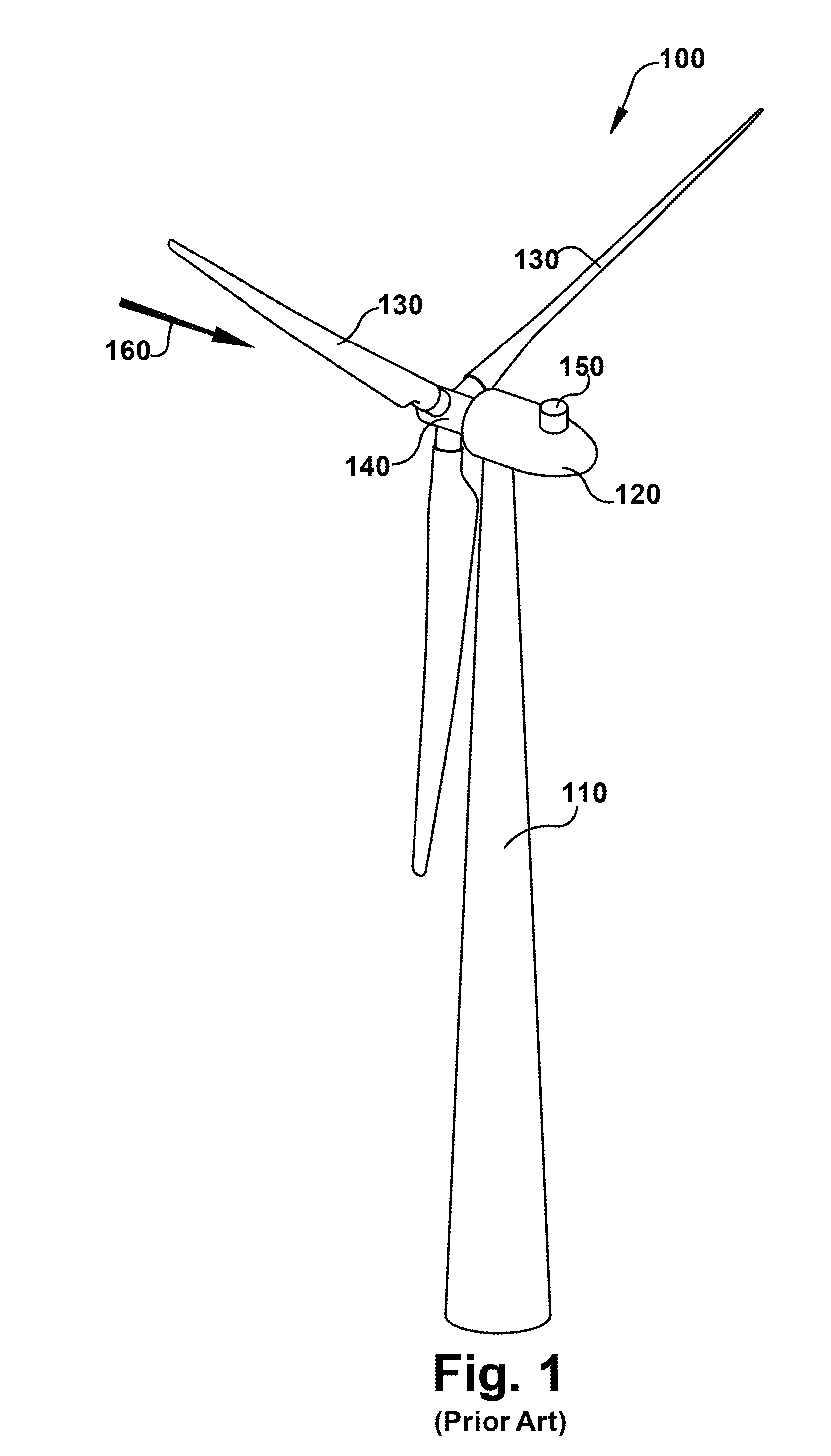
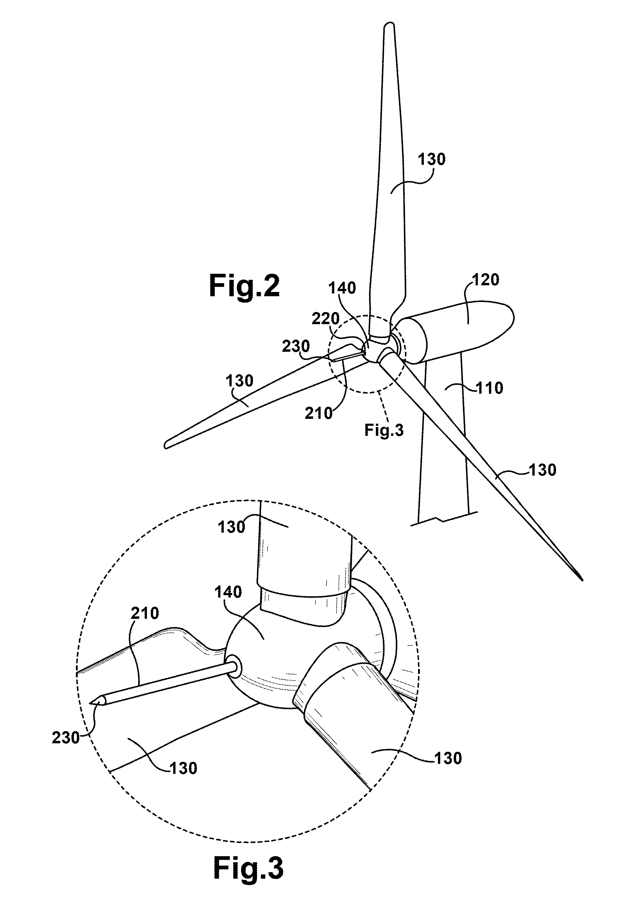
[0025]A typical commercial horizontal axis wind turbine (HAWT), hereafter “wind turbine”, 100 is illustrated in FIG. 1. The wind turbine 100 may include a tubular tower 110, which is often manufactured of steel. The tower 110 may be erected by stacking multiple tower segments on top of each other. The tower 110 supports the weight of the nacelle 120, blades 130 and hub 140. Towers may also be of the lattice (or truss) type, and tubular towers may alternatively be formed of concrete or other suitable materials. The nacelle 120 typically houses the drive train (e.g., gearbox, shafts, couplings, generator, etc.), as well as the main frame (also called bedplate) and yaw drives. Other items such as the control electronics may be housed within the nacelle 120 as well. Typically, the nacelle 120 has an outer skin that is comprised of a lightweight material such as fiberglass or a graphite composite. The main function of the nacelle skin is to protect the contents from the elements (e.g., r...


PUM


Abstract

A wind turbine and system for controlling a wind turbine using a nosecone mounted metrology system is disclosed. The wind turbine comprises at least one wind sensor for determining at least one wind characteristic. The wind sensor is mounted on a boom and located at a predetermined distance outward from the wind turbine nosecone.

Description

BACKGROUND OF THE INVENTION[0001]The apparatus described herein relates generally to metrology systems for wind turbines. More specifically, the apparatus relates to a metrology system located outward from the nosecone of a wind turbine.[0002]Recently, wind turbines have received increased attention as environmentally safe and relatively inexpensive alternative energy sources. Wind turbines do not emit greenhouse gases (GHGs), and therefore, do not contribute to global warming. Wind turbines also allow a country to become more energy independent by the domestic production of electrical energy. With the growing interest in wind generated electricity, considerable efforts have been made to develop wind turbines that are reliable and efficient.[0003]Wind is usually considered to be a fonn of solar energy caused by uneven heating of the atmosphere by the sun, irregularities of the earth's surface, and rotation of the earth. Wind flow patterns are modified by the earth's terrain, bodies ...

Claims


Application Information

Patent Timeline
Patent Type & Authority Applications(United States)
IPC IPC(8): F03D7/02
CPCF03D11/00G01P5/06G01P5/16Y02E10/726G01P13/02Y02E10/722G01P5/245F03D13/20F03D80/00Y02E10/72
Inventor LECLAIR, RYAN M.SCHMITT, THOMAS P.HONOFF, SASKIA G.WILLIAMS, CLINTON L.SIEBERS, THOMAS H.ROGERS, DONALD M.WINSLOW, CHRISTOPHER J.
Owner GENERAL ELECTRIC CO
Why Eureka
Try Eureka