Ultrasonograph for Creating Elastic Image

an elastic image and ultrasonograph technology, applied in the field of ultrasonographs for creating elastic images, can solve the problems of insufficient experience or skill of operators, inability to clearly identify the gradient difference with respect to the minimal portion of the region having similar, and difficulty in determining whether the treatment has been performed, etc., to achieve the effect of assisting identification

Inactive Publication Date: 2009-06-04
HITACHI MEDICAL CORP
View PDF8 Cites 49 Cited by
  • Summary
  • Abstract
  • Description
  • Claims
  • Application Information

AI Technical Summary

Benefits of technology

[0020]In the present invention, besides the elastic image of the tissue graded with hue or brightness, the histogram indicating the elastic distribution of the tissue in the interest region is displayed as the auxiliary elastic information

Problems solved by technology

In the aforementioned case, the operator with insufficient experience or skill may fail to have the correct determination.
However, as mentioned above, it is difficult to clearly identify the gradient diff

Method used


Image

  • Ultrasonograph for Creating Elastic Image
  • Ultrasonograph for Creating Elastic Image
  • Ultrasonograph for Creating Elastic Image

Examples


third embodiment

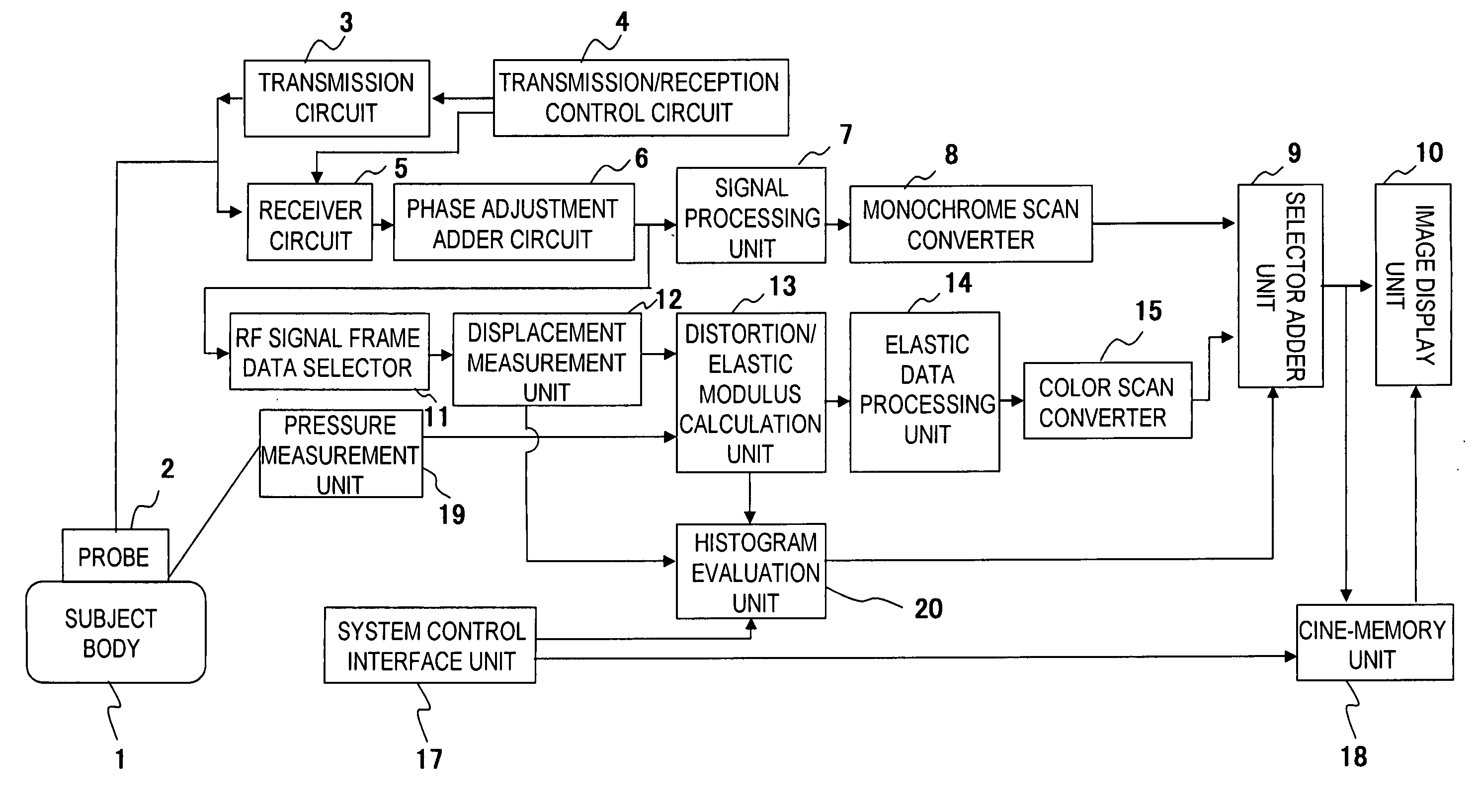
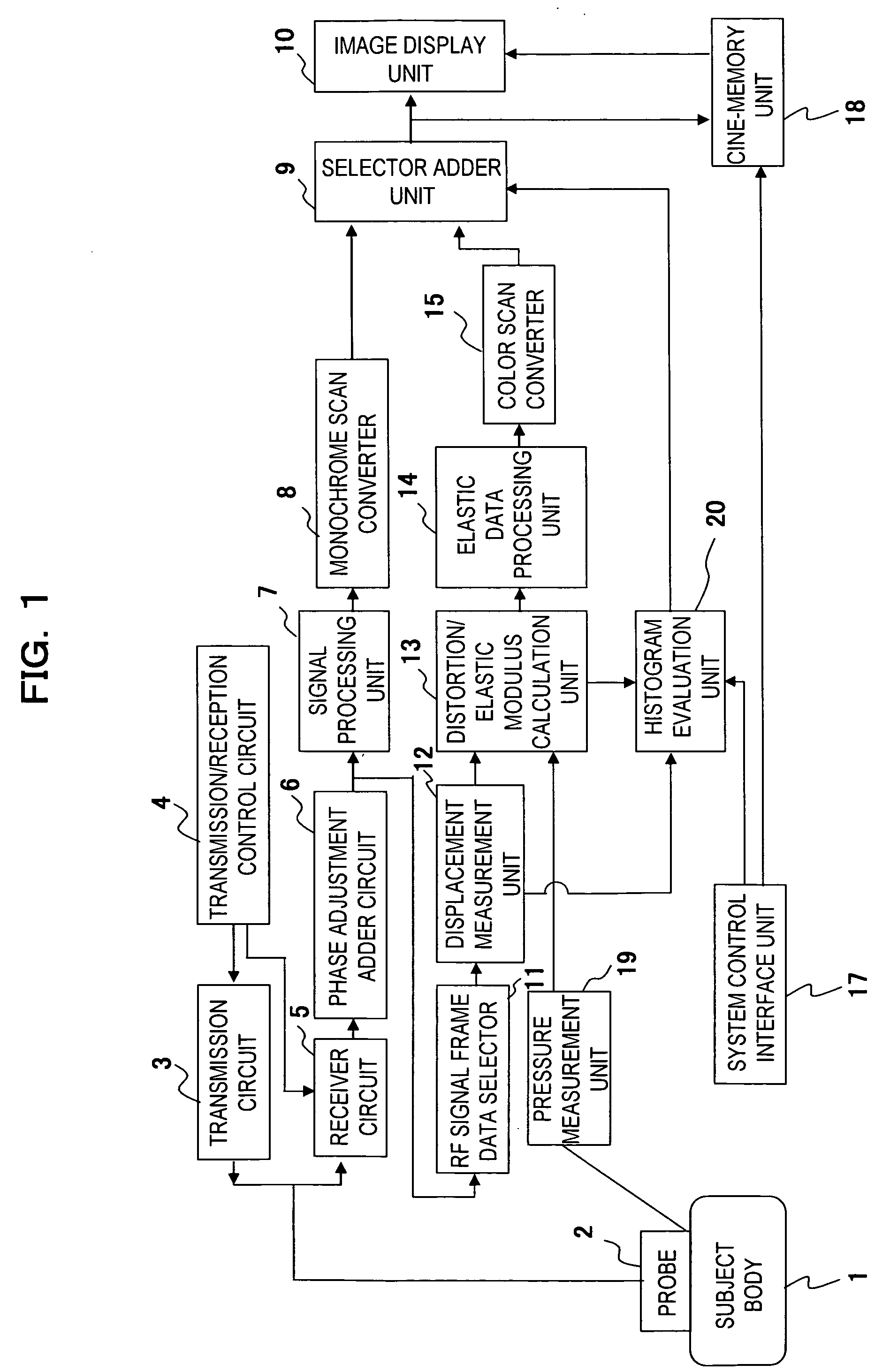
[0096]In the first embodiment, the histogram and the statistic property data are obtained based on the elastic frame data formed of the numeric elastic modulus data calculated by the distortion / elastic modulus calculation unit 13. However, the present invention is not limited to one as described above, the histogram and the statistic property data may be obtained by inputting the elastic frame data subsequent to the image processing in the elastic data processing unit 14 into the histogram evaluation unit 20 such that substantially the same effect as that of the first embodiment may be obtained.

[0097]The histogram and the statistic property data may be obtained based on the elastic image data converted by the color scan converter 15 so as to provide the same effect as that of the first embodiment.

fourth embodiment

[0098]FIG. 10 shows an exemplary display of the histogram image according to a fourth embodiment. In the first embodiment, the histogram is generated based on the elastic modulus as the elastic data correlated with the elasticity so as to be displayed. The present invention is not limited to the one as described above. The obtained histogram is approximated (fitting) with an appropriate function such as double Gaussian or plural Gaussian functions by the statistic evaluation unit 33 so as to be displayed as shown in FIG. 10. In this case, the average and the standard deviation of the respective Gaussian function are obtained, and output as the statistic evaluation data. Referring to the drawing, the fitting function, the elastic modulus m1 to m3 at the peak of the function, or the average M of the elastic modulus and the width information such as the standard deviations σ1 to σ3 may be obtained to be displayed as the property amount data of the histogram.

[0099]Compared with the firs...

fifth embodiment

[0100]FIG. 11 shows an exemplary display of the histogram image according to a fifth embodiment. In the embodiment, the histogram with the arbitrary elastic modulus is designated among those shown in the first embodiment so as to display the specific histogram information. Specifically, plural cursors (C1, C2, . . . ) are displayed on the histogram image data via the input means of the system control interface unit 17 so as to allow the operator to freely move the cursors. The histogram information at the cursor C1, C2, . . . designated by the operator, for example, numeric data such as the number of counts N1, N2, the average value m1, m2 may be displayed in synchronization with the cursor movement.

[0101]The embodiment further allows the operator to evaluate the binding of the target region with the peripheral tissue in terms of the rigidity in the objective and quantitative manner, and makes sure to assist in the tissue identification.


PUM


Abstract

Based on the ultrasonic tomographic data measured by exerting the pressure to the tissue of a body of the subject 1, the elastic data such as the distortion or the elastic modulus of the tissue at the plural measurement points in the tomographic site of the subject body are obtained. Based on the obtained elastic data, the elastic image in the tomographic site is generated to be displayed. The distribution of the elastic data such as the distortion and the elastic modulus in the interest region ROI set on the elastic image is displayed as the histogram. The new quantitative information which reflects the tissue property is supplied in addition to the information which relates to the elasticity of the tissue graded with the hue or brightness for assisting in the tissue identification.

Description

TECHNICAL FIELD[0001]The present invention relates to an ultrasonograph for creating elastic image intended to assist in an appropriate diagnosis by supplying to users an elastic image generated based on the measured elasticity (rigidity or flexibility) of the body tissue of the subject resulting from the compression exerted thereto, and other quantitative information which relates to the elasticity of the tissue.BACKGROUND ART[0002]In the technical field of the ultrasonic diagnostic system, as described in Patent Documents 1 and 2, there has been proposed that the compression is exerted to the subject with the ultrasonic transmission / reception surface of the ultrasonic probe manually or mechanically to obtain displacements of the respective sites in the body through the correlation calculation of the ultrasonic reception signals which closely exist in time-series. Then the elastic data with respect to the tissue elasticity are obtained based on the obtained displacements so as to c...

Claims


Application Information

Patent Timeline
IPC IPC(8): A61B8/00
CPCA61B5/0048A61B8/08A61B8/13A61B8/463A61B8/469G01S7/52084A61B2562/0247A61B2562/046A61N7/00G01S7/52071G01S7/52074A61B8/485A61B5/0053A61B8/4209A61B8/4411A61B8/4444Y02A90/10
Inventor MATSUMURA, TAKESHI
Owner HITACHI MEDICAL CORP
Why Eureka
Try Eureka