Diagnostic of hydraulically switchable engine mechanisms

a technology of hydraulic switchable engine and engine mechanism, which is applied in the direction of instruments, analogue processes for specific applications, electric/magnetic computing, etc., can solve the problems of significant oil leakage, and achieve the effect of reducing the number of lock pin ejections

Inactive Publication Date: 2009-06-04
DELPHI TECH INC
View PDF8 Cites 43 Cited by
  • Summary
  • Abstract
  • Description
  • Claims
  • Application Information

AI Technical Summary

Benefits of technology

[0014]The detection of lock pin failure modes, such as lock pin ejection and operation of the switchable mechanism in low lift mode at elevated engine speeds, may be used in a number of ways. First, the engine controller may adjust the timing of the switch command so as to minimize the number of lock pin ejections. Second, if too many lock pin ejection within a preset time period are detected, the engine controller may indicate a problem, such as by setting diagnostic codes. Third, the number of lock pin ejections for each cylinder may be monitored and the obtained data be used to adjust switch timing in order to distribute lock pin ejections equally across all cylinders, as described, for example, in co-pending U.S. Patent Application Publication No. 2007 / 0256652. Finally, if it is determined one or more of the two-step arms have not switched to high mode during operation at elevated engine speeds, the controller can set a diagnostic code and protect the hardware by adjusting engine parameters to limit the engine speeds until repairs are made.

Problems solved by technology

As the components separate, oil leakage increases significantly.
Second, if too many lock pin ejection within a preset time period are detected, the engine controller may indicate a problem, such as by setting diagnostic codes.

Method used


Image

  • Diagnostic of hydraulically switchable engine mechanisms
  • Diagnostic of hydraulically switchable engine mechanisms
  • Diagnostic of hydraulically switchable engine mechanisms

Examples


first embodiment

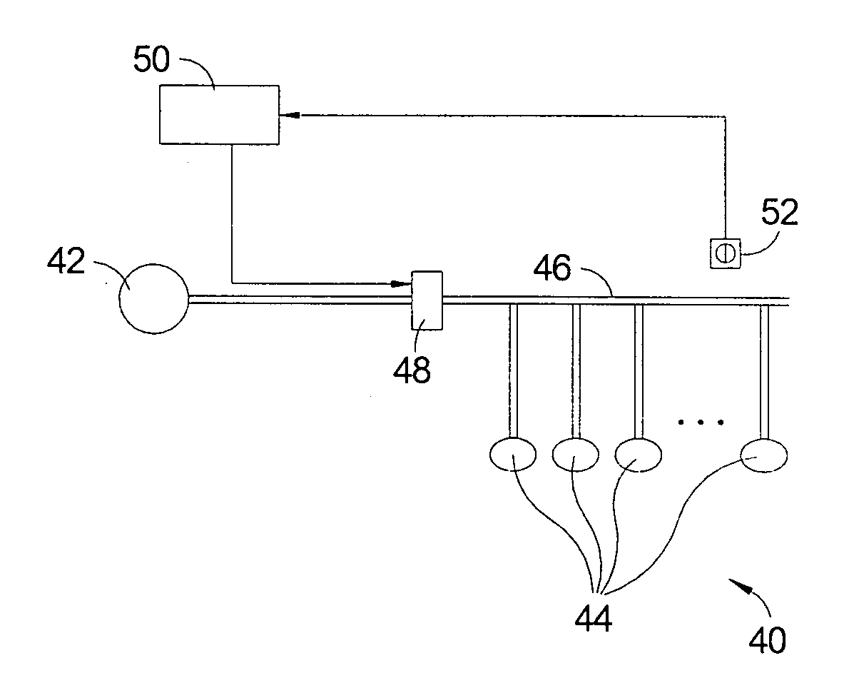
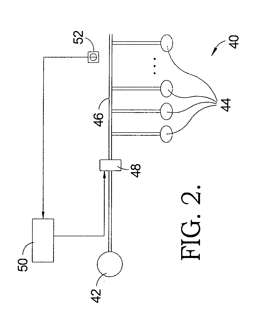
[0031]Referring to FIGS. 3 through 5, diagnostic of a fluid pressure 64 in oil gallery 46 (shown in FIG. 2) is utilized to detect lock pin ejections, in accordance with the invention.

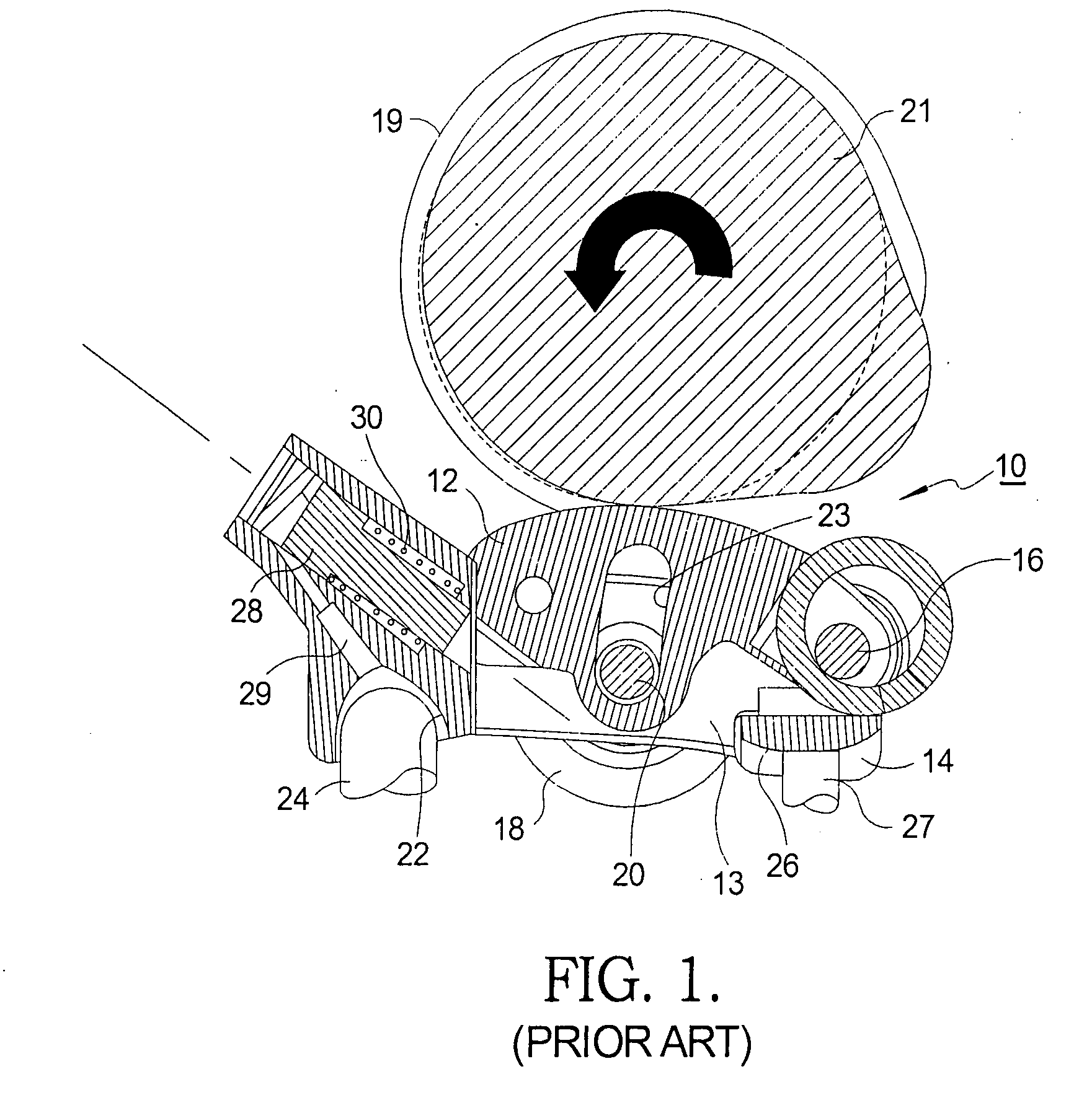
[0032]Graph 60 illustrated in FIG. 3 shows an exemplary relationship between a valve lift 62 and oil pressure 64 of oil gallery 46, and a rotation angle 66 of cam lobe 19 (FIG. 1) corresponding to a lock pin ejection. Trace 68 represents the valve lift associated with two-step RFF 10 (shown in FIG.1) in low lift mode, trace 70 represents the valve lift associated with two-step RFF 10 in high lift mode, and trace 72 represents the pressure in oil gallery 46. The measured oil pressure 64 increases when control valve 48 (FIG. 2) is opened to increase oil pressure 64 to extend lock pin 28 toward a locked position for engagement with inner arm 12 and to switch to high lift mode. As can be seen in a trace 74, lock pin 28 starts to engage with inner arm 12 and RFF 10 starts to operate at high lift mode followi...

second embodiment

[0038]Referring to FIGS. 6 through 8, diagnostic of a fluid pressure 124 in oil gallery 46 (shown in FIG. 2) is utilized in accordance with the invention to detect abnormal operation of a hydraulically switchable variable valve activation system of an internal combustion engine, such as two-step roller finger follower 10 (shown in FIG. 1) at high engine speeds. By comparing the pressure characteristics of normal high speed operation, where all switchable mechanisms 44 (shown in FIG. 2) are operated in high lift mode, to the pressure characteristics actually observed at high engine speeds, abnormal engine operation may be detected, where at least one of the switchable mechanisms 44 is stuck in low lift mode while all other switchable mechanisms 44 are operated in high lift mode. To detect abnormal operation of a hydraulically switchable variable valve activation system of an internal combustion engine at high speeds, the timing of when the controller acquires the pressure data from p...


PUM


Abstract

A method for detecting failure modes of latching mechanisms in a hydraulically switchable variable valve activation system of an internal combustion engine includes the steps of: integrating a pressure sensor in an engine control system including a plurality of switchable mechanisms connected to a common hydraulic gallery, an oil control valve downstream of the oil gallery, and en engine controller activating the oil control valve and the pressure sensor; measuring fluid pressure of the gallery with the pressure sensor; and determining if a failure mode of latching mechanisms occurred by evaluating the measured fluid pressure. Sudden flow changes that produce high frequency fluid pressure oscillations in the oil gallery are detected with the pressure sensor and evaluated by an engine controller to detect lock pin failure modes, such as lock pin ejections and operation of two-step RFF in a low lift mode at elevated engine speeds.

Description

TECHNICAL FIELD[0001]The present invention relates to variable valve activation systems for internal combustion engines; more particularly, to roller finger follower type rocker arm assemblies capable of changing between high and low or no valve lifts; and most particularly, to a method for detecting lock pin failure modes by monitoring the hydraulic pressure in the hydraulic gallery.BACKGROUND OF THE INVENTION[0002]Variable valve activation (VVA) mechanisms for internal combustion engines are well known. It is known to be desirable to lower the lift, or even to provide no lift at all, of one or more valves of a multiple-cylinder engine, during periods of light engine load. Such deactivation or cam profile switching can substantially improve fuel efficiency.[0003]Various approaches are known in the prior art for changing the lift of valves in a running engine. One known approach is to provide a latching mechanism in the roller finger follower (RFF) component of the valve train. The ...

Claims


Application Information

Patent Timeline
Patent Type & Authority Applications(United States)
IPC IPC(8): G01M15/04
CPCG01M15/09
Inventor HENDRIKSMA, NICK J.
Owner DELPHI TECH INC
Why Eureka
Try Eureka