Fuel distribution tube for direct injection fuel rail assemblies

a technology of direct injection and fuel rail, which is applied in the direction of liquid fuel feeders, machines/engines, mechanical equipment, etc., can solve the problems of affecting the reliability of visual inspection, leakage testing may replace less reliable visual inspection, and the leakage of the brazed joint to leakage, etc., and achieve the effect of less reliabl

Inactive Publication Date: 2009-06-11
DELPHI TECH INC
View PDF6 Cites 30 Cited by
  • Summary
  • Abstract
  • Description
  • Claims
  • Application Information

AI Technical Summary

Benefits of technology

[0011]Briefly described, a fuel distribution tube of a direct injection fuel rail assembly includes a plurality of machined scalloped features for receiving a plurality of fuel injector sockets and a plurality of mounting bosses. The scalloped features are designed to closely match the outer radii of the injector sockets and the mounting bosses. The scalloped features provide necessary dimensional control and fuel passage from the fuel distribution tube to the fuel injector sockets. The current need to drill or punch holes into the fuel distribution tube for fuel passage is eliminated in accordance with the present invention due to the formation of a hole when a scalloped feature is formed, for example, by cutting in the fuel distribution tube. A machining process may be used to form all scalloped features into the fuel distribution tube concurrently along a preset tooling centerline. This process allows the use of a mill quality fuel supply tube that is held on the tooling centerline. An ultimate centerline of the scalloped features is the result of the machine h...

Problems solved by technology

During the leak test, the brazed joint would leak if it failed to properly fill.
The...

Method used


Image

  • Fuel distribution tube for direct injection fuel rail assemblies
  • Fuel distribution tube for direct injection fuel rail assemblies
  • Fuel distribution tube for direct injection fuel rail assemblies

Examples


Embodiment Construction

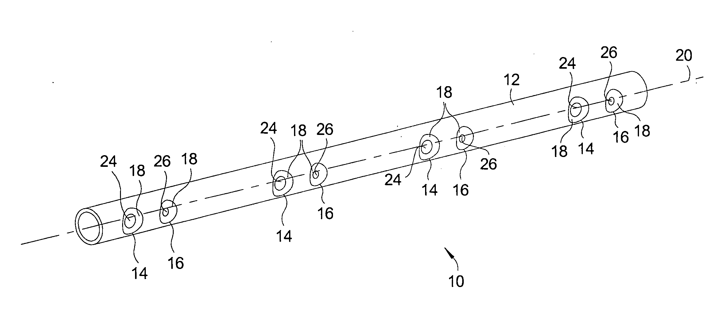
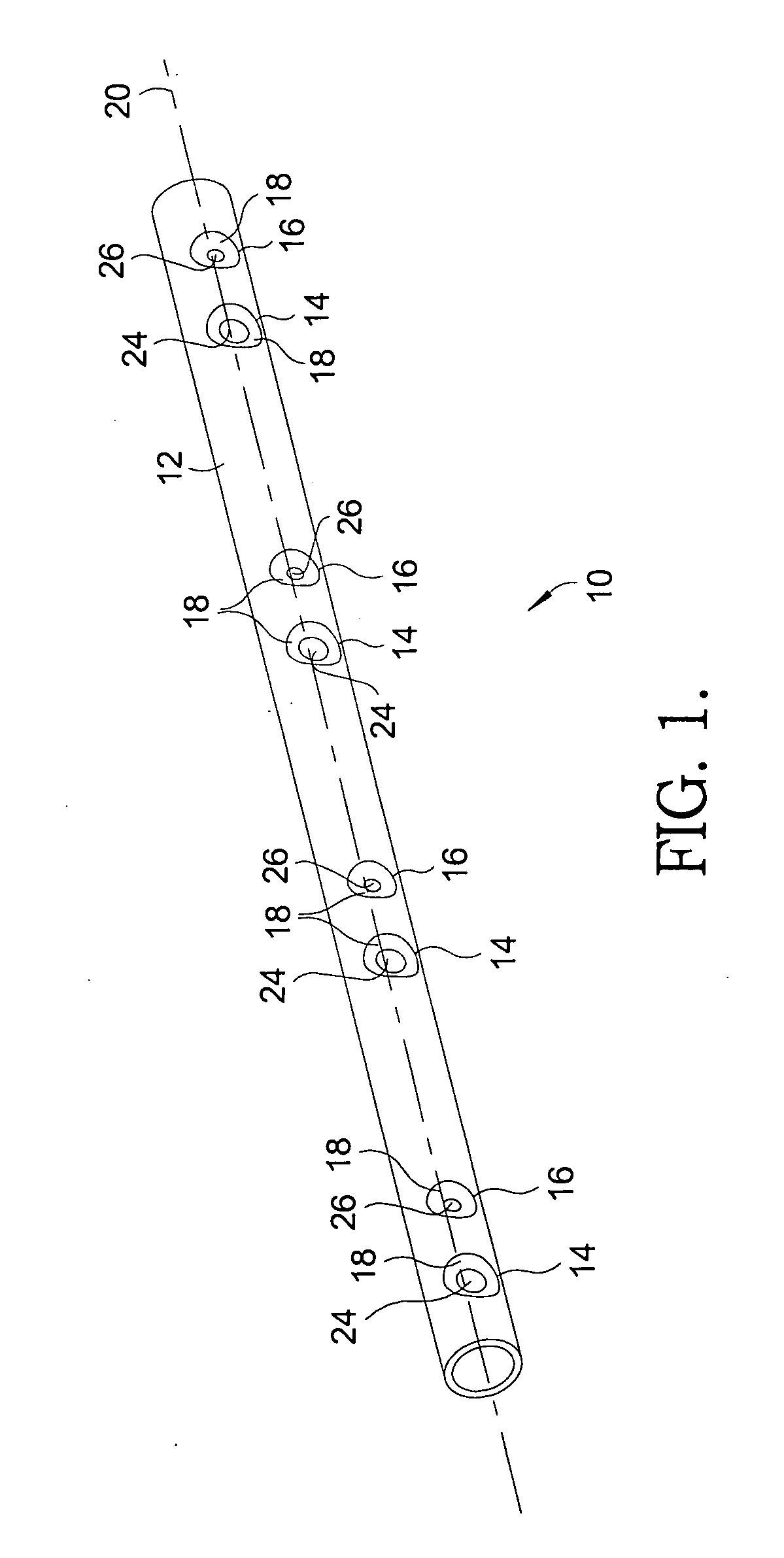
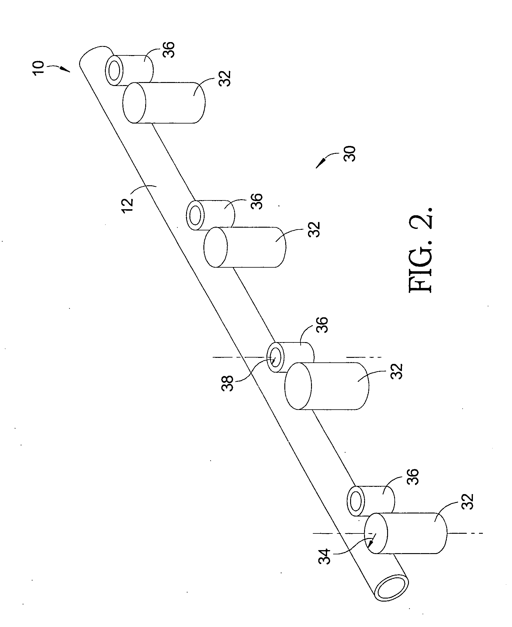
[0020]Referring to FIGS. 1 and 2, a fuel distribution tube 10 includes an elongate cylindrical conduit 12 having a plurality of scalloped features 14 and 16 incorporated. Fuel distribution tube 10 may be part of a direct injection fuel rail assembly of an internal combustion engine, such as assembly 30 shown in FIG. 2. Fuel distribution tube 10 may be connected to a fuel supply (not shown) at one end and may include a cap (not shown) at an opposite end.

[0021]Scalloped features 14 are designed to receive fuel injector sockets 32. Each scalloped feature 14 may be machined, for example, cut into conduit 12 to closely match a radius 34 of fuel injector sockets 32. Scalloped features 16 are designed to receive mounting bosses 36. Each scalloped feature 16 may be machined, for example, cut into conduit 12 to closely match a radius 38 of mounting bosses 36. While scalloped features 14 and 16 as well as fuel injector sockets 32 and mounting bosses 36 are shown in FIGS. 1 and 2, respectively...


PUM


Abstract

A fuel distribution tube for a direct injection fuel rail assembly includes an elongate cylindrical conduit, a plurality of first scalloped features that receive fuel injector sockets formed in the conduit, and plurality of second scalloped features that receive mounting bosses formed in the conduit. The scalloped features are designed to closely match the outer radii of the injector sockets and the mounting bosses. The scalloped features provide necessary dimensional control to injector sockets and mounting bosses and fuel passage from the fuel distribution tube to the fuel injector sockets. The scalloped features enable a leak test of the braze joints of the fuel rail assembly. By providing a direct injection fuel rail assembly that includes the fuel distribution tube having scalloped features formed in the conduit, optimization of true position location of fuel injector sockets and improved braze joints are enabled.

Description

TECHNICAL FIELD[0001]The present invention relates to fuel rail assemblies for supplying fuel to fuel injectors of internal combustion engines; more particularly, to fuel rail assemblies for supplying fuel for direct injection of gasoline (DIG) or of diesel fuel (DID) into engine cylinders; and most particularly, to an improved fuel distribution tube for direct injection fuel rail assemblies.BACKGROUND OF THE INVENTION[0002]Fuel rails for supplying fuel to fuel injectors of internal combustion engines are well known. A fuel rail assembly, also referred to herein simply as a fuel rail, is essentially an elongate tubular fuel manifold connected at an inlet end to a fuel supply system and having a plurality of ports for mating in any of various arrangements with a plurality of fuel injectors to be supplied. Typically, a fuel rail assembly includes a plurality of fuel injector sockets in communication with a manifold supply tube, the injectors being inserted into the sockets and held in...

Claims


Application Information

Patent Timeline
IPC IPC(8): F16L9/02
CPCF02M55/025F02M2200/8084F02M65/003
Inventor COLLETTI, MICHAEL J.DUELL, KRISTOPHER J.
Owner DELPHI TECH INC
Why Eureka
Try Eureka