Image sensing apparatus

Inactive Publication Date: 2009-06-11
MITSUBISHI ELECTRIC CORP
View PDF9 Cites 10 Cited by
  • Summary
  • Abstract
  • Description
  • Claims
  • Application Information

AI Technical Summary

Benefits of technology

[0015]In the image sensing apparatus according to the present invention, a compact image sensing apparatus can be provided by repeatedly reflecting, in an alternate direction, light beams in the casing even in a long optical path, notwiths

Problems solved by technology

Furthermore, a problem has been that in the apparatus as disclosed in Japanese Unexamined Patent Publication H5-328024, there is a need for a focusing optical element 42 that makes variable a focus

Method used


Image

  • Image sensing apparatus
  • Image sensing apparatus
  • Image sensing apparatus

Examples


embodiment 1

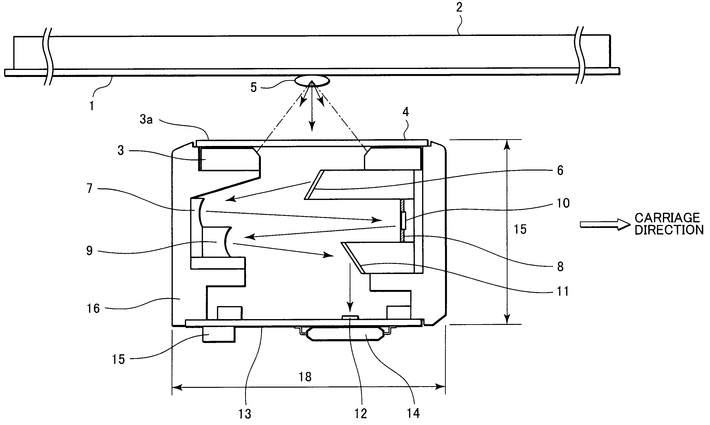
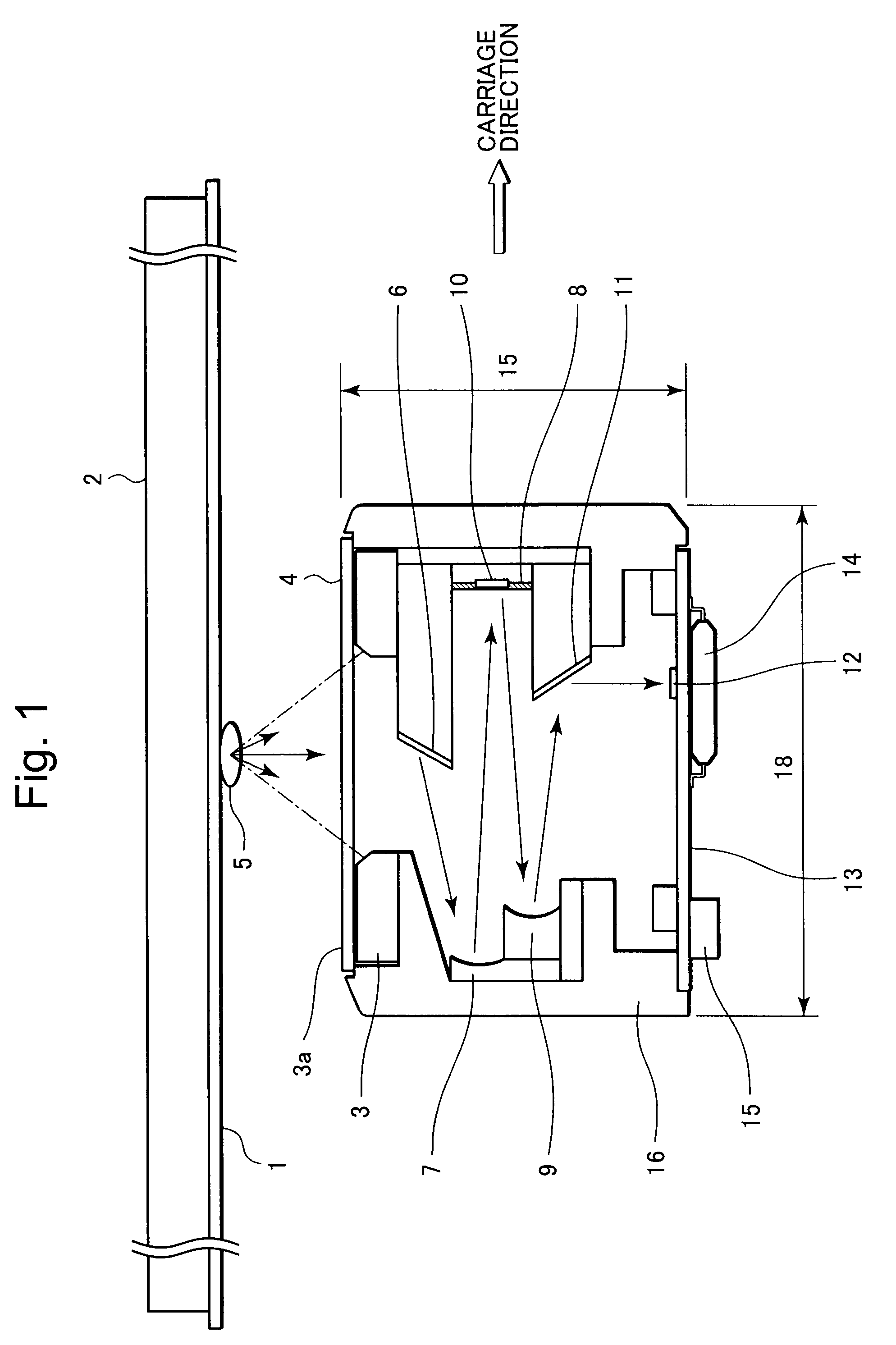
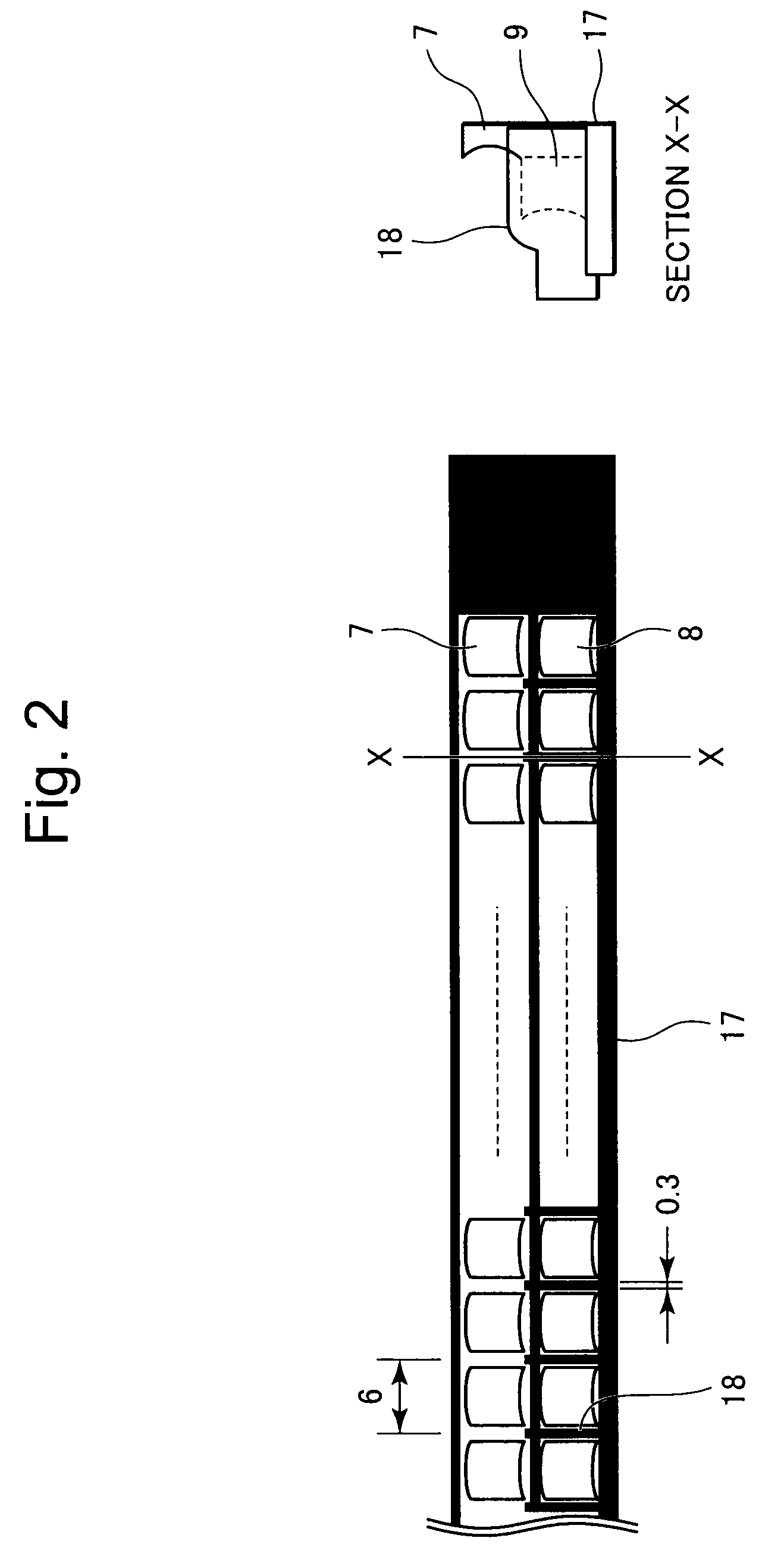
[0042]An image sensing apparatus in accordance with Embodiment 1 of the present invention will be described below with reference to FIG. 1. FIG. 1 is a schematic diagram illustrating an internal view of the image sensing apparatus in accordance with Embodiment 1 of the present invention. Referring to FIG. 1, an illuminated object (referred to as a paper sheet) such as a document or a medium, is indicated at numeral 1; a platen 2 supports the illuminated object 1; light guides 3 transmit light beams; light-emitting portions of the light guides 3 are indicated at numeral 3a; the light beams pass through a light transmission member 4; an illumination portion of the illuminated object 1 is indicated at numeral 5; a first mirror 6 reflects in a secondary scan direction scattered light incident from the illumination portion 5; first concaved lens mirrors 7 (also referred to as first lenses, or first aspheric mirrors) receive the light beams reflected from the first mirror 6; an aperture m...

embodiment 2

[0061]As has been described in Embodiment 1, the light beams from both-end light sources are shone on the illuminated object 1 by using the rod-like light guides 3, while in Embodiment 2, an array light source is used, as will be described below. FIG. 18 is a schematic diagram illustrating a cross-sectional view of the image sensing apparatus in accordance with Embodiment 2 of the present invention. In FIG. 18, a vertical light guide 130 transmits a light beam; a light-emitting portion of the light guide 130 is indicated at numeral 130a. A cover 140 is comprised of a plastic material having a slit, through which the light beams pass, in the neighborhood of the illumination portion 5 and constitutes part of a carriage path of the illuminated object 1; a first mirror 160 reflects scattered light incident from the illumination portion 5; first concaved lens mirrors 170 (first lenses) each receive the light beams reflected from the first mirror 160; an aperture mirror 180 receives colli...

embodiment 3

[0069]In Embodiment 1 and Embodiment 2, each light source of the RGB signals is illuminated concurrently and then image information are read; in Embodiment 3, a different LED light source is used, as will be described below. Here, detailed operating description of the image sensing apparatus according to Embodiment 3 is omitted because the description of Embodiment 1 applies to Embodiment 3.

[0070]FIG. 23 is a schematic diagram illustrating light source portions including the light guide. In FIG. 23A, a light scatter layer 250 uniformly shines the light beams across the entire range in the primary scan direction from the light emitting section 3a of the light guide 3; electrode sections 260 each are disposed separately at either side of the light guide 3; and light sources 270 each include an LED chip that emits a violet light wavelength of 405 nm or more.[0046] In addition, FIG. 23B is partially enlarged view of the neighborhood of the electrode section 260 in FIG. 23A; the light so...


PUM


Abstract

An image sensing apparatus having a large depth of focus (DOF) and being compact in size is provided. The image sensing apparatus includes a plurality of light sources that shines light beams on an illumination portion of a document; a first mirror that receives incident light scattered by reflection from the document, to reflect the scattered light in the secondary scan direction; a plurality of first concaved aspheric mirrors that collimates light beams from the first mirror, to reflect therefrom the collimated light beams as substantially collimated light fluxes; an aperture mirror that reflects therefrom the light beams from the respective first aspheric mirrors, through apertures each having a light-shielded portion formed therearound and selectively passing the light beams therethrough; a plurality of second concaved aspheric mirrors that receives the light beams incident from the respective aperture mirror, to reflect the incident light beams as converging light beams; a second mirror that reflects the light beams in a direction perpendicular to the surface of the document, disposed on a path of the light beams to be converged by means of the second aspheric mirrors; a plurality of light receivers each having a light-receiving area that receives the light beams from the second mirrors, to form images according to the light beams from the respective apertures; and a casing where the first and second aspheric mirrors are disposed on a first side of the casing in the secondary scan direction, and the aperture mirror is disposed on a second side thereof in the secondary scan direction.

Description

FIELD OF THE INVENTION[0001]The present invention relates to image sensing apparatuses that are used for image sensing or identification devices such as photocopiers or financial terminals, respectively.BACKGROUND OF THE INVENTION[0002]For example, Japanese Unexamined Patent Publication H11-8742 (FIG. 2) discloses a sensing apparatus that utilizes a mirror array, as an image sensing apparatus that senses image information.[0003]In addition, Japanese Unexamined Patent Publication 2003-331267 (see FIG. 2) discloses an image sensing device having a telecentric optical system and an illumination system that are suited to test on one-time primary scanning of a plurality of testing portions being present on a mounting substrate.[0004]Furthermore, Japanese Unexamined Patent Publication H5-328024 discloses that an image sensing apparatus includes a light source lamp 24 that shines light beams on a sensing object G; optical means 20 and 30 for transmitting light beams reflected by the sensin...

Claims


Application Information

Patent Timeline
IPC IPC(8): H04N1/04
CPCH04N1/02815H04N1/02835H04N1/0318H04N1/1017H04N2201/03145H04N2201/03112H04N2201/03129H04N2201/03137H04N1/193
Inventor MINOBE, TADASHIKAWANO, HIROYUKIMIKAMI, IZUMIENDO, TAKAFUMI
Owner MITSUBISHI ELECTRIC CORP
Why Eureka
Try Eureka