Lubricator for Rolling Bearings

a technology for lubricating rollers and rolling bearings, which is applied in the direction of bearing cooling, rolling contact bearings, shafts and bearings, etc., can solve the problems of increasing power loss, achieve stable suppression of cooling oil flow, improve sealability, and reduce the resistance of cooling oil

Inactive Publication Date: 2009-06-11
NTN CORP
View PDF0 Cites 13 Cited by
  • Summary
  • Abstract
  • Description
  • Claims
  • Application Information

AI Technical Summary

Benefits of technology

[0011]With the lubricator for rolling bearings according to the present invention, since the gap between the radially outer surface of the inner ring and the seal portion is set at 0.2 mm or less, it is possible to stably suppress the amount of cooling oil flowing into the bearing, thereby reducing the resistance of cooling oil when the oil is agitated during high-speed rotation of the bearing.
[0012]Also, with the lubricator for rolling b

Problems solved by technology

This increases

Method used


Image

  • Lubricator for Rolling Bearings
  • Lubricator for Rolling Bearings
  • Lubricator for Rolling Bearings

Examples


examples

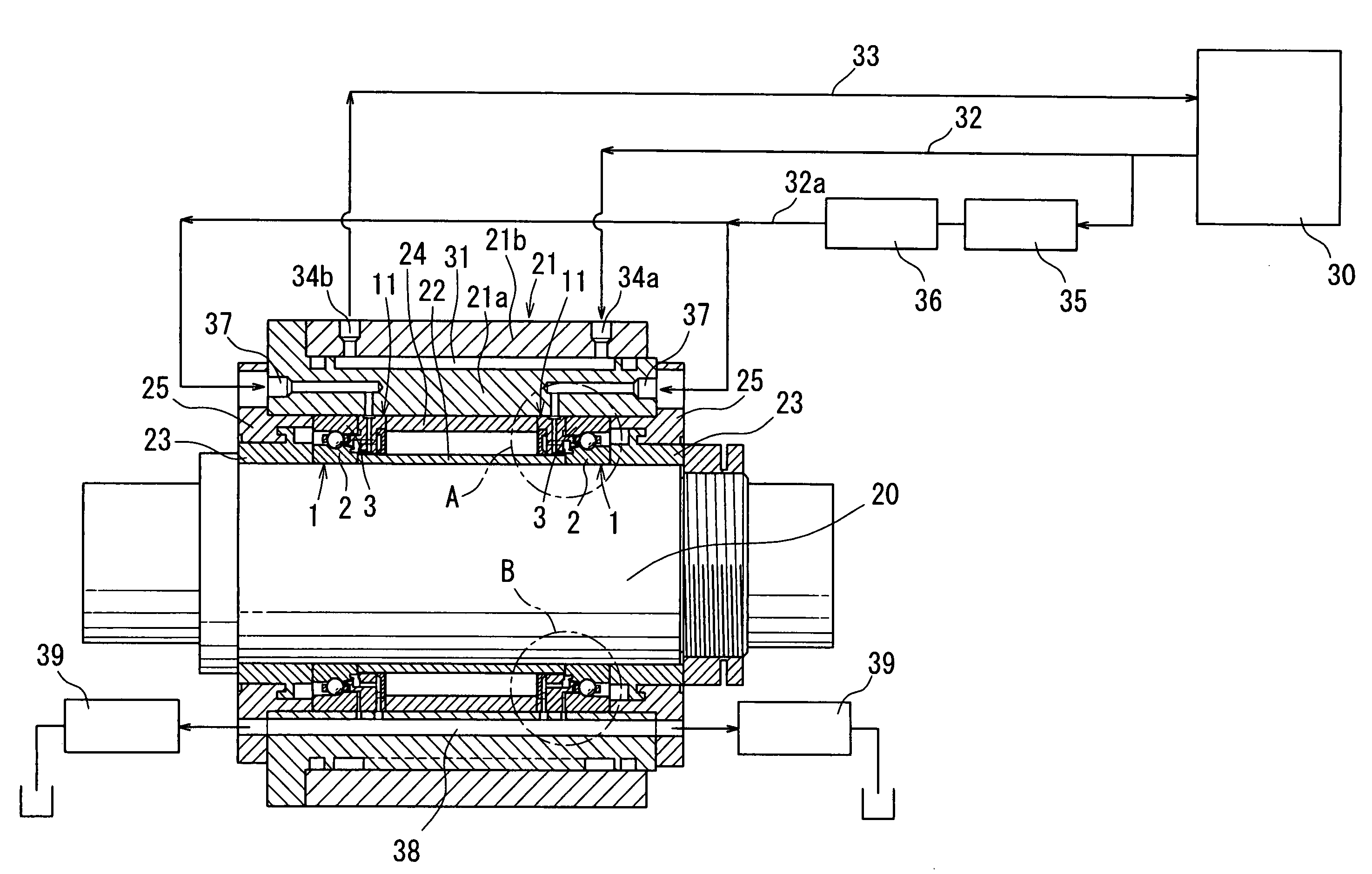
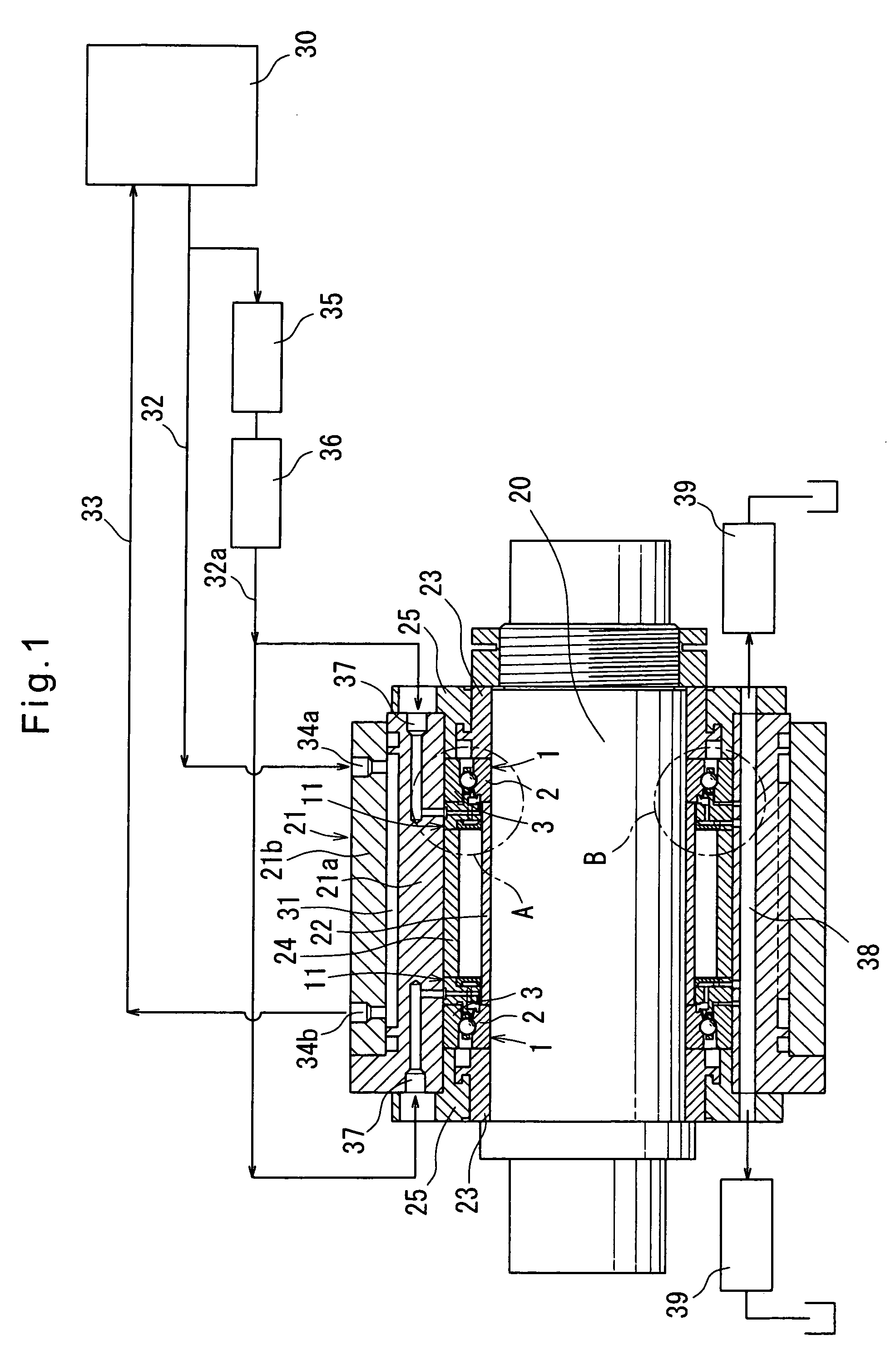
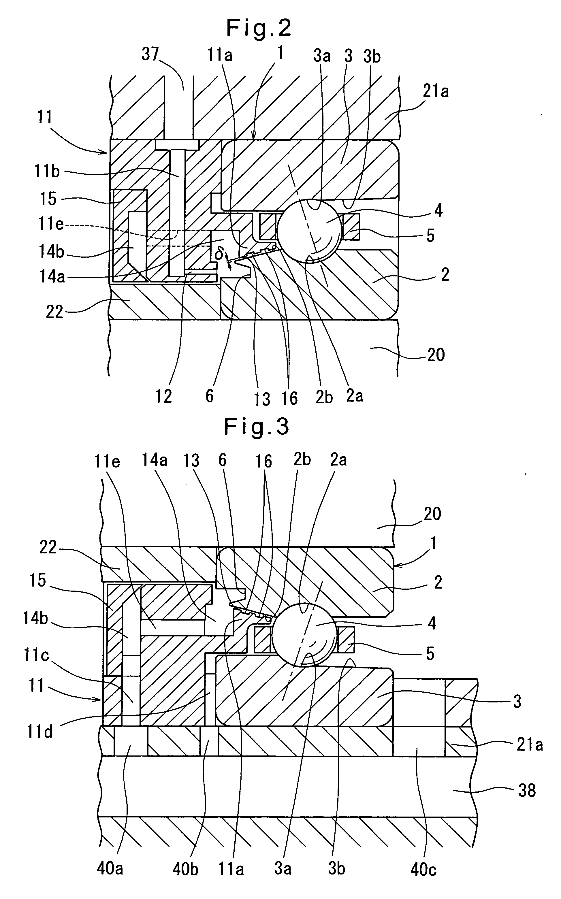
[0066]The amount Q of cooling oil discharged through the nozzle 12 and flowing through the seal portion 13 into the interior of the bearing as lubricating oil was measured when the gap δ of the seal portion 13 shown in FIG. 2 was changed. The diameter of the spindle 20 (inner diameter of the angular ball bearings 1) was 70 mm, its revolving speed was 30000 rpm, and the amount of cooling oil discharged through the nozzle 12 was 0.6 liters / minute.

[0067]The results of measurement of the amount Q are shown in FIG. 4. As is apparent from these measurement results, while the gap δ is 0.2 mm or less, the amount Q was small and remained substantially unchanged. But when the gap δ exceeded 0.2 mm, the amount Q began to increase sharply. Thus, by setting the gap δ at the seal portion at 0.2 mm or less, it is possible to stably suppress the amount Q of cooling oil flowing into the interior of the bearing, thereby reducing the resistance of cooling oil when the oil is agitated during high-speed...


PUM


Abstract

The object is to provide a lubricator for rolling bearings which is also capable of cooling the inner ring and which can reduce the resistance of cooling oil when the oil is agitated during high-speed rotation of the bearing.
On the back side of an angular ball bearing 1, a cooling oil introducing member 11 is provided which includes a nozzle 12 for discharging cooling oil toward a circumferential groove 6 formed in an end surface of an inner ring 2. The cooling oil introducing member 11 has an extension 11a formed with a seal portion 13 that faces a tapered surface 2b of the inner ring with a gap δ left therebetween. The gap δ of the seal portion is set at 0.2 mm or less to limit the amount of cooling oil that flows through the seal portion 13 into the bearing to a minimum, thereby reducing the resistance of cooling oil when the oil is agitated during high-speed rotation of the angular ball bearing 1.

Description

TECHNICAL FIELD[0001]The present invention relates to a lubricator for rolling bearings which is also capable of cooling an inner ring of a bearing.BACKGROUND ART[0002]When a rolling bearing is used to support a rotary shaft rotating at a high speed such as a spindle of a machine tool, the inner ring is heated to a higher temperature than the outer ring due e.g. to machining loads. Due to this temperature difference, the inner and outer rings expand to different degrees, thus excessively increasing the preload applied to the bearing. This in turn shortens the lifespan of the bearing.[0003]In order to cope with this problem, lubricators for rolling bearings are known (see e.g. Patent document 1) which are configured to discharge cooling oil supplied from a cooling oil feeder toward the inner rotary ring of a rolling bearing from one end of the bearing, and have a seal portion facing the radially outer surface of the inner ring at one end thereof toward which cooling oil is discharged...

Claims


Application Information

Patent Timeline
IPC IPC(8): F16C33/66F16C37/00
CPCF16C19/548F16C33/667F16N2210/14F16C35/12F16C33/6674
Inventor SASABE, MITSUOMORI, MASATSUGU
Owner NTN CORP
Why Eureka
Try Eureka