
Brewery plant and method

a technology for brewing plants and brewing methods, applied in indirect heat exchangers, machines using solar energy, light and heating equipment, etc., can solve the problems of not being independent of price increases and energy costs, and achieve the effect of facilitating an ideal supply of energy for individual loads

Inactive Publication Date: 2009-06-11
KRONES AG
View PDF38 Cites 16 Cited by
  • Summary
  • Abstract
  • Description
  • Claims
  • Application Information

AI Technical Summary

Benefits of technology

[0005]Therefore, the object of the present disclosure is to provide a brewery plant and a brewing method to render the breweries more independent of the requirement for fossil fuels.
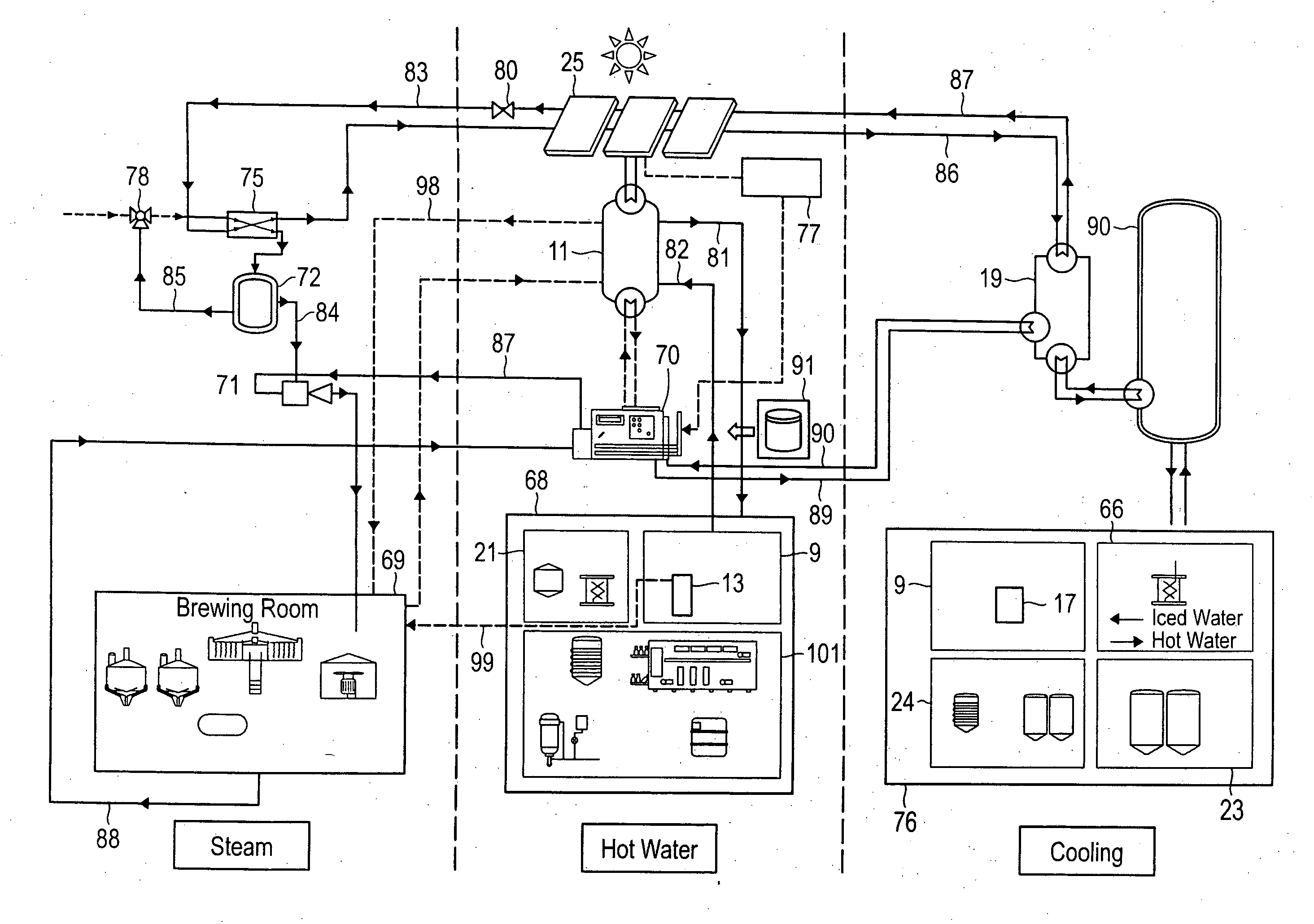
[0009]According to a preferred embodiment, to provide cooling the brewery can have a sorptive refrigerating plant, the thermal energy requirement of which is at least partially covered by the thermal energy produced by the solar collectors. Conventionally in breweries compression refrigeration systems are used, which however have the same disadvantages as conventional heat generators. In contrast the use of a sorptive refrigerating plant has the advantage that the thermal energy generated by the solar collectors can also be used for producing the required cooling.
[0013]The disclosure also relates to a brewing method where the thermal energy requirement of at least part of the brewing process stages, in particular during mashing, lautering and / or wort boiling, is at least partially covered by a fluid which is directly or indirectly heated by solar collectors to a temperature of at least 120° C., in particular to a temperature in a range from 160° C. to 180° C. Through the use of thermal energy from solar radiation the dependence on conventional thermal energy generators can be reduced. In order to make the method more efficient than in the conventional generation of energy it is particularly important that the fluid can be heated to the highest temperatures which are used in the process. In this respect the fluid can be heated both directly as well as indirectly.
[0014]According to a preferred embodiment the thermal energy requirement for bottle cleaning can at least be partially covered by a fluid heated directly or indirectly by solar collectors to a temperature of at least 120° C., in particular to a temperature in a range from 160° C. to 180° C. The advantageous use of solar energy is thus not just restricted to the actual brewing process, but rather it can be used in the whole beer production. In particular, in the bottle room the energy requirement during bottle cleaning is high, so that the use of solar energy is advantageous.
[0017]This embodiment has the advantage that if the power from the solar collectors is not sufficient, for example due to reduced solar radiation resulting from poor weather or due to the time of day, a high-speed steam generating device can be switched in. Thus, it is ensured that sufficient thermal energy can be fed to the individual thermal loads even with reduced solar radiation. A high-speed steam generating device is characterized in that it can quickly generate vapor, in particular steam, to compensate a power deficit from the solar collectors. The high-speed steam generating device is in particular advantageous, because it can be operated, for example, by regenerative energy sources via a district heating power station, rendering the plant overall independent of non-regenerative energy sources, in particular fossil fuels.
[0024]This concept enables steam thermal loads, hot-water thermal loads and simultaneously refrigeration loads (through the use of an absorption refrigeration plant) to be used via the fluid which is heated to a temperature of over 120°. This overall concept, in particular in combination with the high-speed steam generating device facilitates an ideal supply of the individual loads with energy in a simple manner.

Problems solved by technology

Taken overall the energy costs represent a considerable share of the total production costs of beer.
Since they are however similarly based on fossil fuels, they are also not independent of price increases due to the shortage of fossil fuels.

Method used


Image

  • Brewery plant and method
  • Brewery plant and method
  • Brewery plant and method

Examples


Embodiment Construction

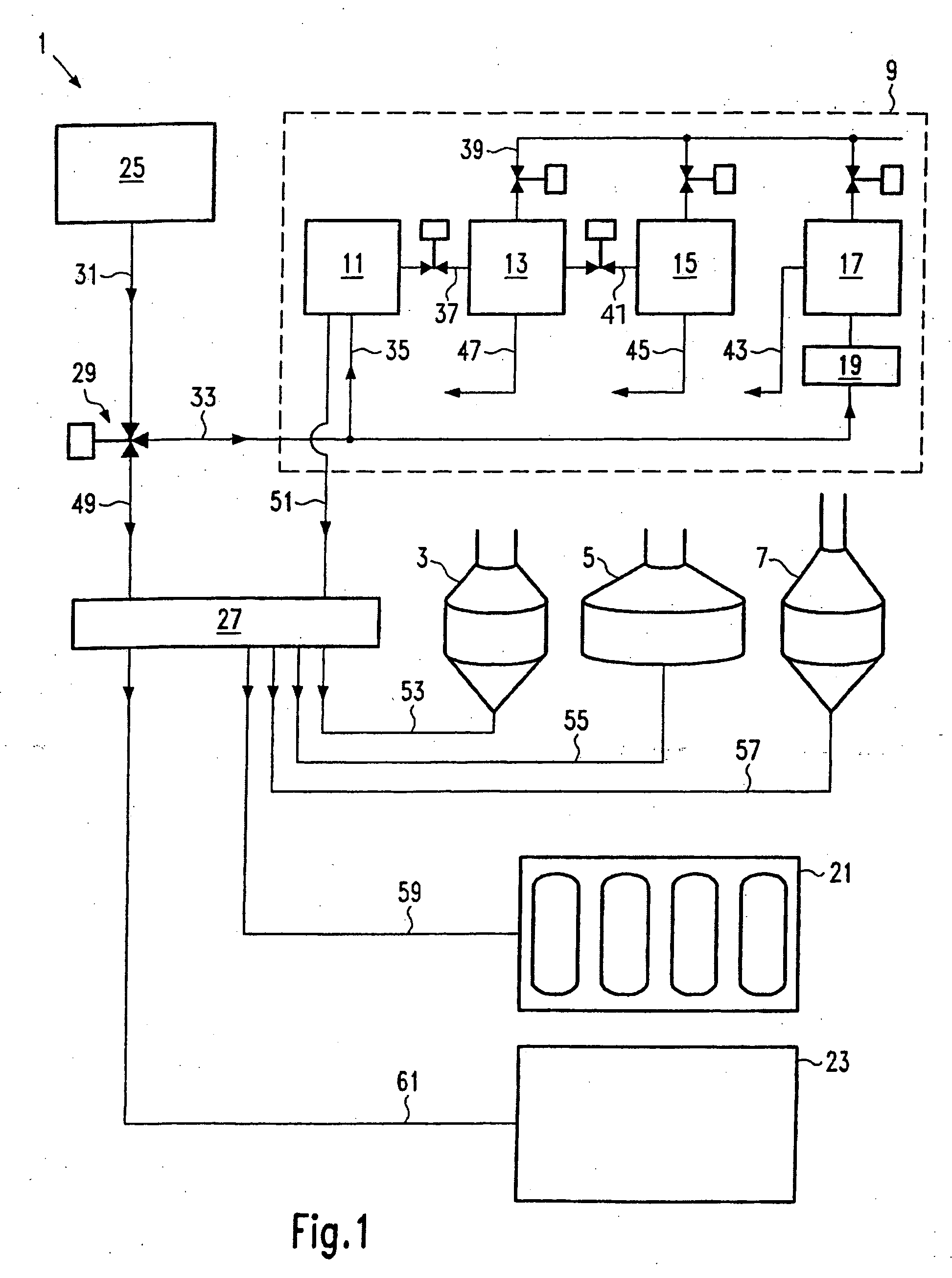
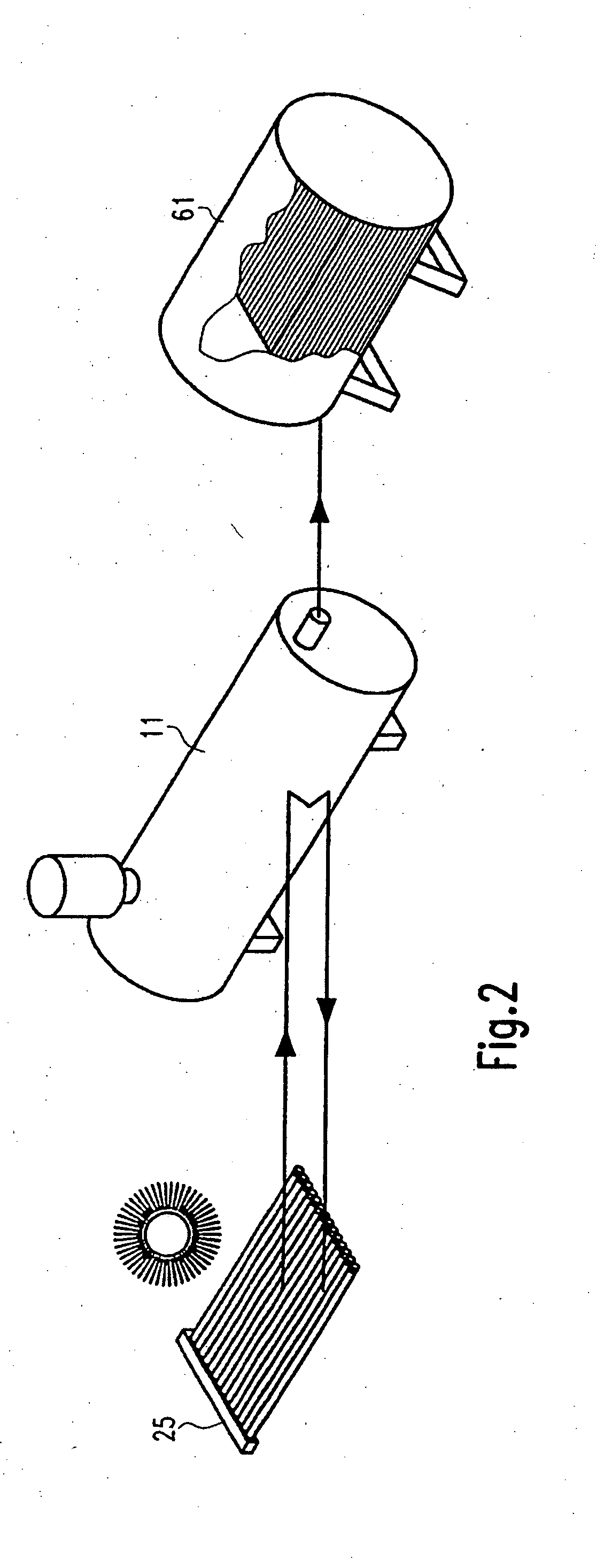
[0038]FIG. 1 shows a brewery plant 1 with a mash container 3, lauter tun 5, wort pan 7 and a water housing 9. The water housing 9 comprises several heat accumulators: a high-pressure hot-water tank 11, suitable for fluid temperatures of at least 120° C., in particular from 160° C. to 180° C., a warm-water tank 13, a cold-water tank 15 and an iced-water tank 17. A sorptive refrigerating plant 19 is used to produce the iced water. In addition the brewery plant 1 also has a CIP (Cleaning In Process) system 21. This system is used for the cleaning and disinfection of the brewery plant 1. Furthermore, a bottle room 23 is schematically illustrated. Here the bottling equipment and the bottle cleaning equipment for the brewery are located. Finally, the solar collectors 25 are illustrated in FIG. 1. They are used to cover at least part of the thermal energy requirement of the brewery 1. The solar collectors 25 are designed such that a fluid is directly or indirectly heated with the aid of th...


PUM

PropertyMeasurementUnit
temperatureaaaaaaaaaa

Abstract

A brewery plant with at least one mash container, a lauter tun, a wort pan and a water housing, wherein at least part of the thermal energy requirement of the brewery is covered with solar collectors, and the solar collectors directly or indirectly heat a fluid. Also, a brewing method where the thermal energy requirement for at least of a part of the brewing process stages is at least partially covered with a fluid heated directly or indirectly by solar collectors.

Description

CROSS-REFERENCE TO RELATED APPLICATION[0001]The present application claims the benefit of priority of International Patent Application No. PCT / EP2006 / 002638 filed on Mar. 22, 2006, which application claims priority of European Patent Application No. 05006424.5 filed Mar. 23, 2005. The entire text of the priority application is incorporated herein by reference in its entirety.FIELD OF THE DISCLOSURE[0002]The disclosure relates to a brewery plant with at least one mash container, a lauter tun, a wort pan and a water housing, and to a brewing method, all utilizing solar power for thermal energy.BACKGROUND[0003]Brewing beer is a process which requires a great deal of energy, wherein both electrical energy and thermal energy are required. Taken overall the energy costs represent a considerable share of the total production costs of beer. As a trend it must be assumed that the share of the energy costs will increase further due to the shortage of fossil fuels and the higher energy prices ...

Claims


Application Information

Patent Timeline
Patent Type & Authority Applications(United States)
IPC IPC(8): C12C13/00F24J2/12F25B27/00F22B27/00F24S23/71
CPCC12C13/00F24J2/42F28D2020/006F28D20/00F28D20/0039F25B27/007F24S90/00Y02P60/85
Inventor STIPPLER, KURTWASMUHT, KLAUS-KARL
Owner KRONES AG
Learn More