Vapor-phase process apparatus, vapor-phase process method, and substrate

a technology of vapor phase and process equipment, which is applied in the direction of crystal growth process, polycrystalline material growth, transportation and packaging, etc., can solve the problems of difficult optimization of flow rate or flow velocity distribution of flow-guide gas depending on process types, and the conventional vapor-phase process apparatus described above has suffered, etc., to achieve the effect of suppressing the adhesion of foreign substances, and reducing the amount of reaction gas

Inactive Publication Date: 2009-06-11
SUMITOMO ELECTRIC IND LTD
View PDF38 Cites 25 Cited by
  • Summary
  • Abstract
  • Description
  • Claims
  • Application Information

AI Technical Summary

Benefits of technology

[0020]Thus, the gas that flows along the surface of the wall portion forms a gas layer on the surface of the wall portion. This gas layer reduces the amount of the reaction gas reaching the surface of the wall portion of the process chamber (such as the surface of the wall portion opposed to the process object). Consequently, in the processing step, an amount of deposits on the surface of the wall portion can be reduced. Accordingly, the amount of foreign substances such as deposit frakes from the surface of the wall, which adhere to the surface of the process object, can be lowered. Therefore, lower process quality due to adhesion of such foreign substances can be suppressed.
[0021]In addition, formation of a uniformly flowing gas layer as described above on the surface of the wall portion brings about a noticeable effect of increase in flow velocity of the reaction gas in a downstream of the direction of the reaction gas flow. Accordingly, a process rate in the downstream (for example, in the case of a film deposition process, a film growth rate) can be increased. Therefore, when a susceptor rotation or the like is employed as well, uniformity of a process on the substrate (such as uniformity of a thickness or quality of the formed film) can be ensured.
[0022]A substrate according to the present invention is a substrate manufactured with the vapor-phase process method above. As the substrate is thus subjected to a uniform process, an excellent substrate surface layer (for example, a film formed on the surface of the substrate) can be obtained.
[0023]As described above, according to the present invention, process quality such as process uniformity can be improved, and consequently a substrate of excellent quality can be obtained.

Problems solved by technology

The conventional vapor-phase process apparatus described above, however, has suffered from the following problems.
In addition, in the apparatus shown in FIG. 1 of Japanese Patent Laying-Open No. 2005-005594, the flow-guide gas is supplied from a common gas supply source to the plurality of flow-guide gas blowing portions and a flow rate or the like cannot be controlled individually for each flow-guide gas blowing portion.
In the conventional vapor-phase process apparatus described above, however, if types of such processes are changed, it is difficult to optimize a flow rate or flow velocity distribution of the flow-guide gas depending on types of processes.
Accordingly, it has been difficult to satisfactorily maintain process quality (for example, quality of a formed film), such as a rate of film deposition on the substrate surface and uniformity of a composition of a formed film.
Further, according to Japanese Patent Laying-Open Nos. 2002-371361 and 2006-013326, a plurality of nozzles supply the pressing gas (the flow-guide gas), however, these gases may not form such a gas layer as uniformly covering a wall portion (an upper wall) of the process chamber.
When such deposits peel off from the upper wall (the wall portion) and result in deposit pieces, the deposit pieces may adhere to the surface of the process object, which results in large number of defects.

Method used


Image

  • Vapor-phase process apparatus, vapor-phase process method, and substrate
  • Vapor-phase process apparatus, vapor-phase process method, and substrate
  • Vapor-phase process apparatus, vapor-phase process method, and substrate

Examples


embodiment 1

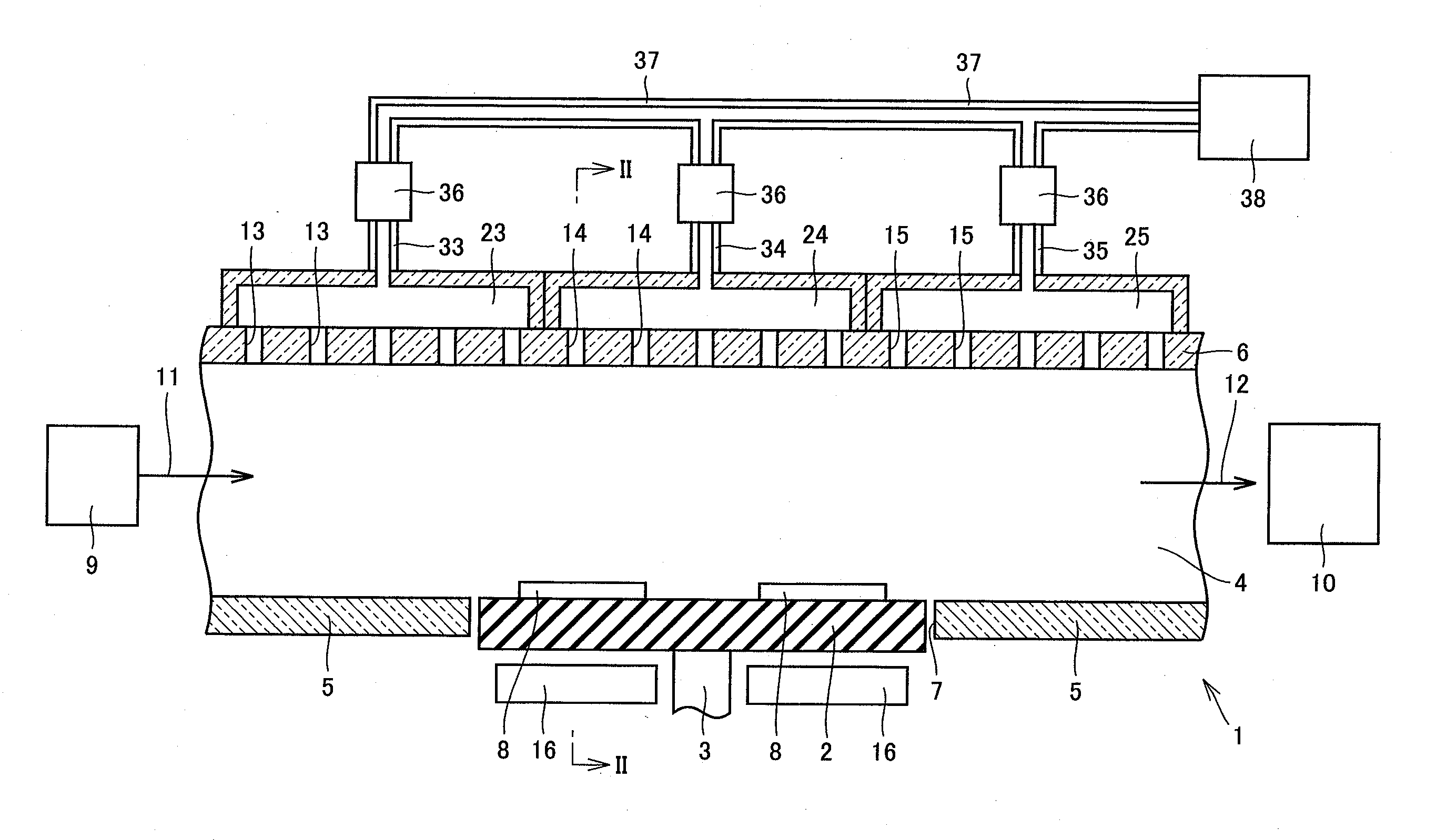
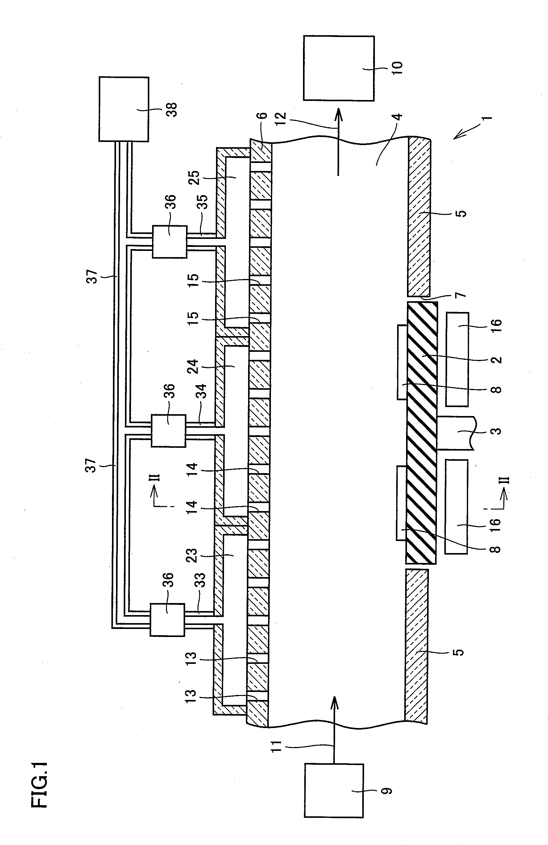
[0046]Embodiment 1 of a vapor-phase process apparatus according to the present invention will be described with reference to FIGS. 1 and 2.

[0047]As shown in FIGS. 1 and 2, a vapor-phase process apparatus 1 is a vapor-deposition apparatus, and it includes a process chamber 4, a susceptor 2 located in an opening 7 formed in a bottom wall 5 of process chamber 4, a reaction gas supply member 9, a gas exhaust member 10, a heater 16, and a gas supply portion for supplying a purge gas into process chamber 4. This gas supply portion is specifically constituted of a gas supply member 38, a pipe 37 connected to gas supply member 38, a flow rate control device 36 connected to pipe 37, and buffer chambers 23 to 25 supplied with a gas (a purge gas) from flow rate control device 36 through pipes 33 to 35. In order to supply the gas from these buffer chambers 23 to 25 into process chamber 4, gas supply ports 13 to 15 serving as a plurality of gas introduction portions are formed in an upper wall 6...

embodiment 2

[0070]Embodiment 2 of the vapor-phase process apparatus according to the present invention will be described with reference to FIG. 7.

[0071]Vapor-phase process apparatus 1 shown in FIG. 7 has a structure basically the same as that of the vapor-phase process apparatus shown in FIGS. 1 and 2, however, it is different in that a height of process chamber 4 gradually decreases from the upstream toward the downstream in the direction of flow of the reaction gas. Namely, in vapor-phase process apparatus 1 shown in FIG. 7, arrangement is such that upper wall 6 of process chamber 4 is slightly inclined to come closer to bottom wall 5 from the upstream side toward the downstream side in the direction shown with arrow 11 indicating the direction of flow of the reaction gas (the direction of supply). According to such a structure as well, an effect the same as in the vapor-phase process apparatus shown in FIGS. 1 and 2 can be achieved.

[0072]In addition, in vapor-phase process apparatus 1 shown ...

embodiment 3

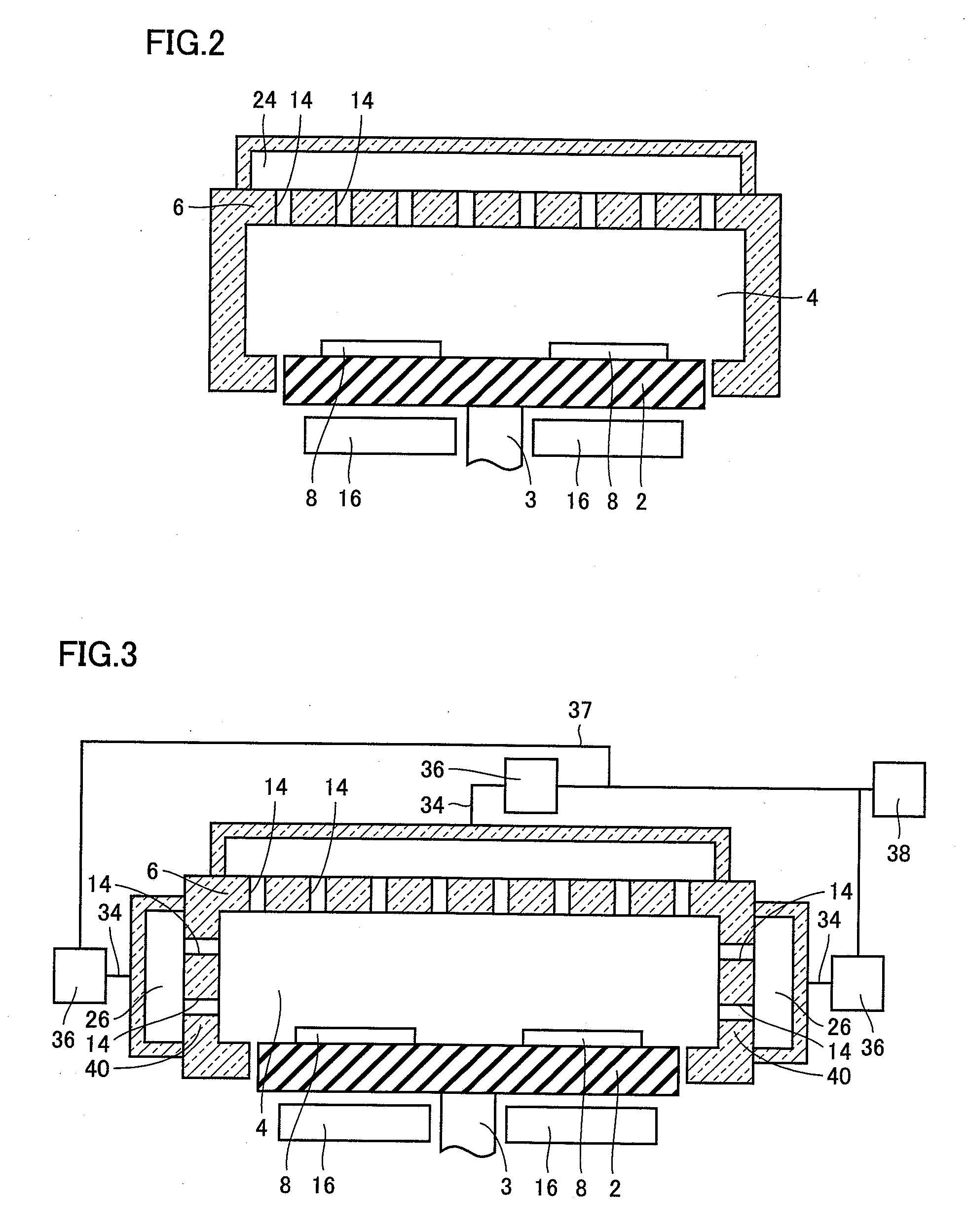
[0073]Embodiment 3 of the vapor-phase process apparatus according to the present invention will be described with reference to FIG. 8.

[0074]Vapor-phase process apparatus 1 shown in FIG. 8 has a structure basically the same as that of the vapor-phase process apparatus shown in FIGS. 1 and 2, however, it is different from the vapor-phase process apparatus shown in FIGS. 1 and 2 in a structure of a gas supply portion formed on upper wall 6 and a structure of susceptor 2. Specifically, in vapor-phase process apparatus 1 shown in FIG. 8, four buffer chambers 23 to 26 are arranged in line along a direction of flow of the reaction gas shown with arrow 11. Buffer chambers 23 to 26 are connected to gas supply member 38 through respective independent flow rate control devices 36 via pipes 37.

[0075]In addition, susceptor 2 in vapor-phase process apparatus 1 shown in FIG. 8 can carry three substrates 8 along the direction of flow of the reaction gas above. In FIG. 8, substrate 8 located in the ...


PUM

PropertyMeasurementUnit
angleaaaaaaaaaa
thicknessaaaaaaaaaa
diameteraaaaaaaaaa

Abstract

A vapor-phase process apparatus and a vapor-phase process method capable of satisfactorily maintaining quality of processes even when different types of processes are performed are obtained. A vapor-phase process apparatus includes a process chamber, gas supply ports serving as a plurality of gas introduction portions, and a gas supply portion (a gas supply member, a pipe, a flow rate control device, a pipe, and a buffer chamber). The process chamber allows flow of a reaction gas therein. The plurality of gas supply ports are formed in a wall surface (upper wall) of the process chamber along a direction of flow of the reaction gas. The gas supply portion can supply a gas into the process chamber at a different flow rate from each of one gas supply port and another gas supply port different from that one gas supply port among the plurality of gas supply ports.

Description

BACKGROUND OF THE INVENTION[0001]1. Field of the Invention[0002]The present invention relates to a vapor-phase process apparatus, a vapor-phase process method, and a substrate, and more particularly to a vapor-phase process apparatus, a vapor-phase process method, and a substrate capable of achieving high-quality process.[0003]2. Description of the Background Art[0004]A vapor-phase process apparatus for such a process as formation of a film on a surface of an object to be processed (hereinafter referred to as a “process object”) such as a substrate has conventionally been known (see, for example, Japanese Patent Laying-Open Nos. 2005-005594, 2002-371361 and 2006-013326). In the vapor-phase process apparatus disclosed, for example, in FIG. 1 of Japanese Patent Laying-Open No. 2005-005594, a plurality of flow-guide gas blowing portions are formed in positions (in an upper wall of a process chamber) opposed to the process object (substrate) arranged in a process chamber (a chamber). Th...

Claims


Application Information

Patent Timeline
Patent Type & Authority Applications(United States)
IPC IPC(8): B32B9/04C23C16/455C23C16/06C23C16/00
CPCC23C16/4401C23C16/45517C23C16/45519C23C16/45565C23C16/455C30B29/403H01J37/3244H01J37/32449H01J37/32541C30B25/165Y10T428/31504
Inventor TAKASUKA, EIRYOUEDA, TOSHIOKURAMOTO, TOSHIYUKIUENO, MASAKI
Owner SUMITOMO ELECTRIC IND LTD
Why Eureka
Try Eureka