Method and arrangement for locating a mobile terminal in a multicell radio arrangement

a multi-cell radio and mobile terminal technology, applied in the direction of electrical equipment, wireless communication, etc., can solve the problems of increasing the energy consumption of the mobile terminal, reducing the data throughput of the radio arrangement, and associated locating of the mobile terminal

Active Publication Date: 2009-06-11
UNIFY GMBH & CO KG
View PDF15 Cites 14 Cited by
  • Summary
  • Abstract
  • Description
  • Claims
  • Application Information

AI Technical Summary

Benefits of technology

[0016]The regular operation of the radio base stations and thus of the multicell radio arrangement is reproduced as quickly as possible when the radio base stations which have been switched to a different radio channel for the measurement are switched back to their original radio channel once the measurement has been carried out (switched back), and any data transmissions which may have been interrupted for the measurement process are continued.

Problems solved by technology

The described methods for recording and locating mobile terminals are associated with disadvantages because mobile terminals, in contrast to the—stationary—radio base stations, generally do not transmit any periodic identification signals or other transmissions when they are not actively transmitting data.
Admittedly, mobile terminals can in many cases be configured such that they transmit such radio signals continuously or quasi-continuously, although this disadvantageously increases the energy consumption of the mobile terminals.
This avoids the same radio channel having to be selected all the time in all the radio base stations in the multicell radio arrangement for location purposes, which, although technically feasible, would, however, lead to a reduced data throughput in the radio arrangement.

Method used


Image

  • Method and arrangement for locating a mobile terminal in a multicell radio arrangement
  • Method and arrangement for locating a mobile terminal in a multicell radio arrangement

Examples


Embodiment Construction

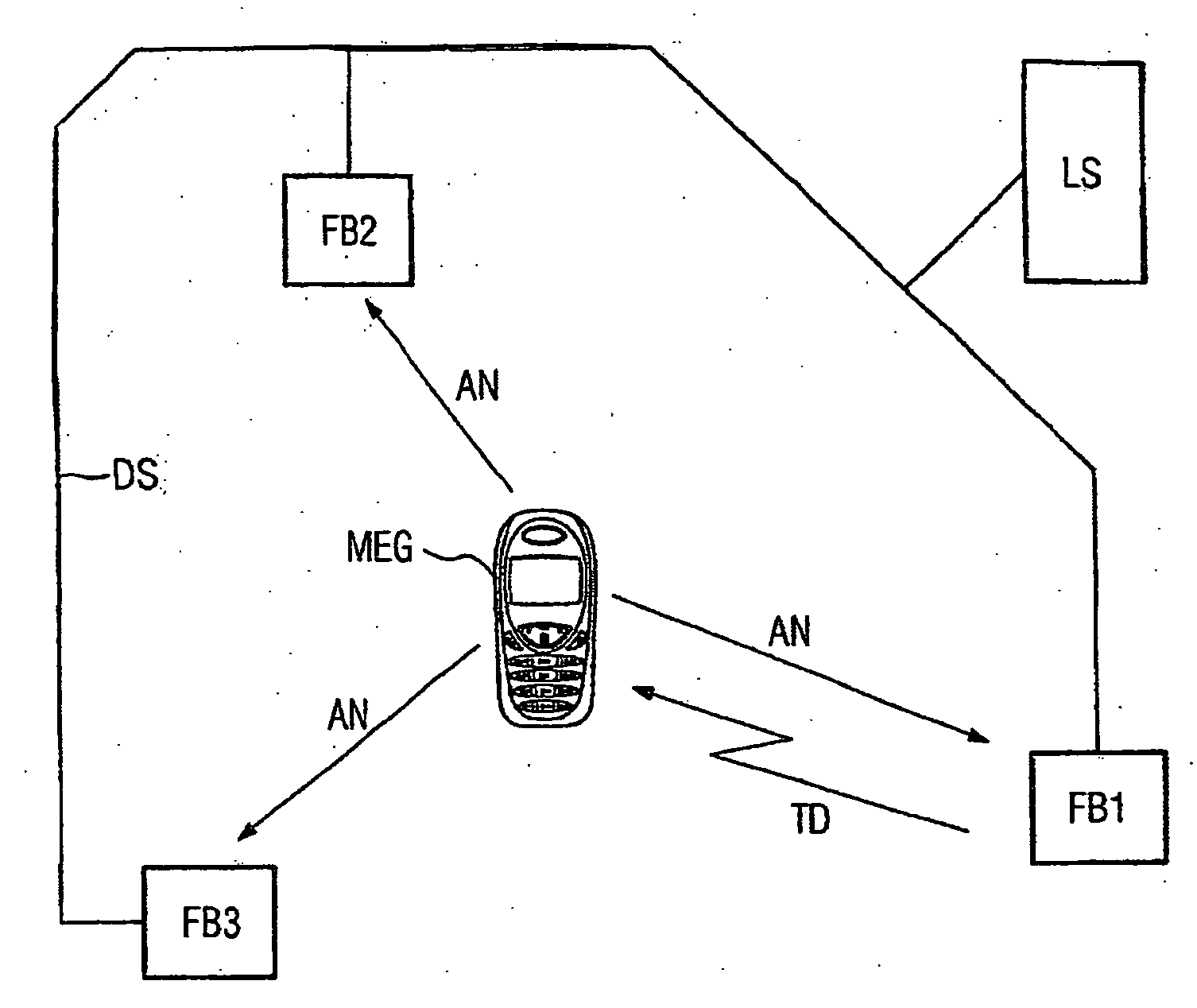
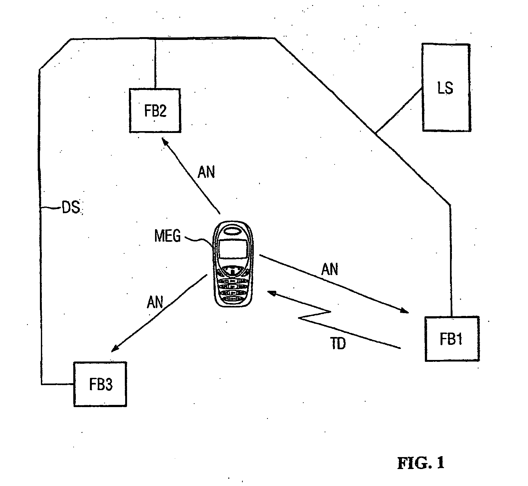
[0022]The FIGURE shows a WLAN network to the IEEE Standard 802.11 as a multicell radio arrangement. In this network, the radio base stations FB1, FB2, FB3 (so-called access points) and a central device LS (location server) are connected to one another via a data network DS (distribution system), a local area network based on the Internet Protocol. The FIGURE also shows a mobile terminal MEG, for example a so-called PDA (personal digital assistant), with WLAN transmitting / receiving device.

[0023]The radio base stations FB1, FB2, FB3 are designed such that they can be instructed by the central server LS to signal to the central server LS the received field strength with which a mobile terminal MEG is received. In addition, the radio base stations FB1, FB2, FB3 may be instructed by the central server LS to temporarily change to an undefined radio channel of the WLAN standard being used.

[0024]It is, of course, also possible to use a different multicell radio arrangement with associated m...


PUM


Abstract

A method and system for locating a mobile terminal in a multicell radio system are provided. A plurality of radio base stations detect the field strength of a data transmission of the mobile terminal and the location of the mobile terminal is determined the values are provided. The mobile terminal is switched into an active state, then a plurality of the radio base stations are set to the radio channel used by the mobile terminal to be located, and the mobile terminal is prompted to emit a response message as a result of the communication of a test data transmission. The received field strength of the received response message is measured by the radio base stations and communicated to a central device, after which the location of the mobile terminal is determined by the central device on the basis of the measured values.

Description

CROSS REFERENCE TO RELATED APPLICATIONS[0001]This application is the US National Stage of International Application No. PCT / EP2006 / 065409, filed Aug. 17, 2006 and claims the benefit thereof. The International Application claims the benefits of German application No. 102005041453.2 DE filed Aug. 31, 2005, both of the applications are incorporated by reference herein in their entirety.FIELD OF INVENTION[0002]The invention relates to a method for locating a mobile terminal in a multicell radio arrangement and to an arrangement for locating a mobile terminal.BACKGROUND OF INVENTION[0003]In modern communication environments, there is a frequent requirement to locate a user and his associated communication terminal, that is to say to determine his position. In line-switching communication networks, for example in “traditional” telephone systems, one specific connection (telephone number) is generally permanently associated with one specific location (for example a connecting box, “connect...

Claims


Application Information

Patent Timeline
Patent Type & Authority Applications(United States)
IPC IPC(8): H04W64/00
CPCH04W64/00
Inventor LUERS, JURGEN
Owner UNIFY GMBH & CO KG
Why Eureka
Try Eureka