
Fuel injector and fuel injection device having same

a fuel injector and fuel injection technology, which is applied in the direction of electrical control, process and machine control, instruments, etc., can solve the problems of insufficient gaseous fuel supply infrastructure of a station, limited reduction of combustion dependent on conventional fossil liquid fuel, and limited high-pressure accumulation or large sizing of fuel storage tanks,

Inactive Publication Date: 2009-06-11
DENSO CORP
View PDF0 Cites 51 Cited by
  • Summary
  • Abstract
  • Description
  • Claims
  • Application Information

AI Technical Summary

Problems solved by technology

In development of a next-generation automobile, greater importance is given to reduction in environmentally hazardous substances (NOx, CO2, PM or the like) in combustion exhaust gases, but the combustion dependent on the conventional fossil liquid fuel has a limitation to the reduction.
However, the fuel storage tank, which can be actually mounted in a commercial vehicle, has a limitation with respect to the high-pressure accumulation or the large sizing.
In addition, infrastructure of a station for gaseous fuel supply is still insufficient in so far.
Therefore, it is more difficult for the gaseous fuel engine to secure a sufficient travel distance as compared to a liquid fuel engine such as gasoline or light oil engine.
On the other hand, for further reduction in combustion exhaust emissions even in an engine using the conventional fossil fuel, a gasoline engine has difficulties in improving of a fuel economy compared to that of a diesel engine.
By contrast, a diesel engine has difficulties in improving of exhaust purification compared with that of the gasoline engine.
However, since the ignition in the HCCI engine depends on an ignition temperature specific to the fuel, it is difficult to control the ignition timing.
In consequence, knocking tends to easily occur in a high-load region, and sufficient mixing of air and fuel is not performed due to lack of the mixing time in a high-rotation-speed region.
Therefore, an operation region of the HCCI engine is limited to a low-load region and a low-rotation-speed region.
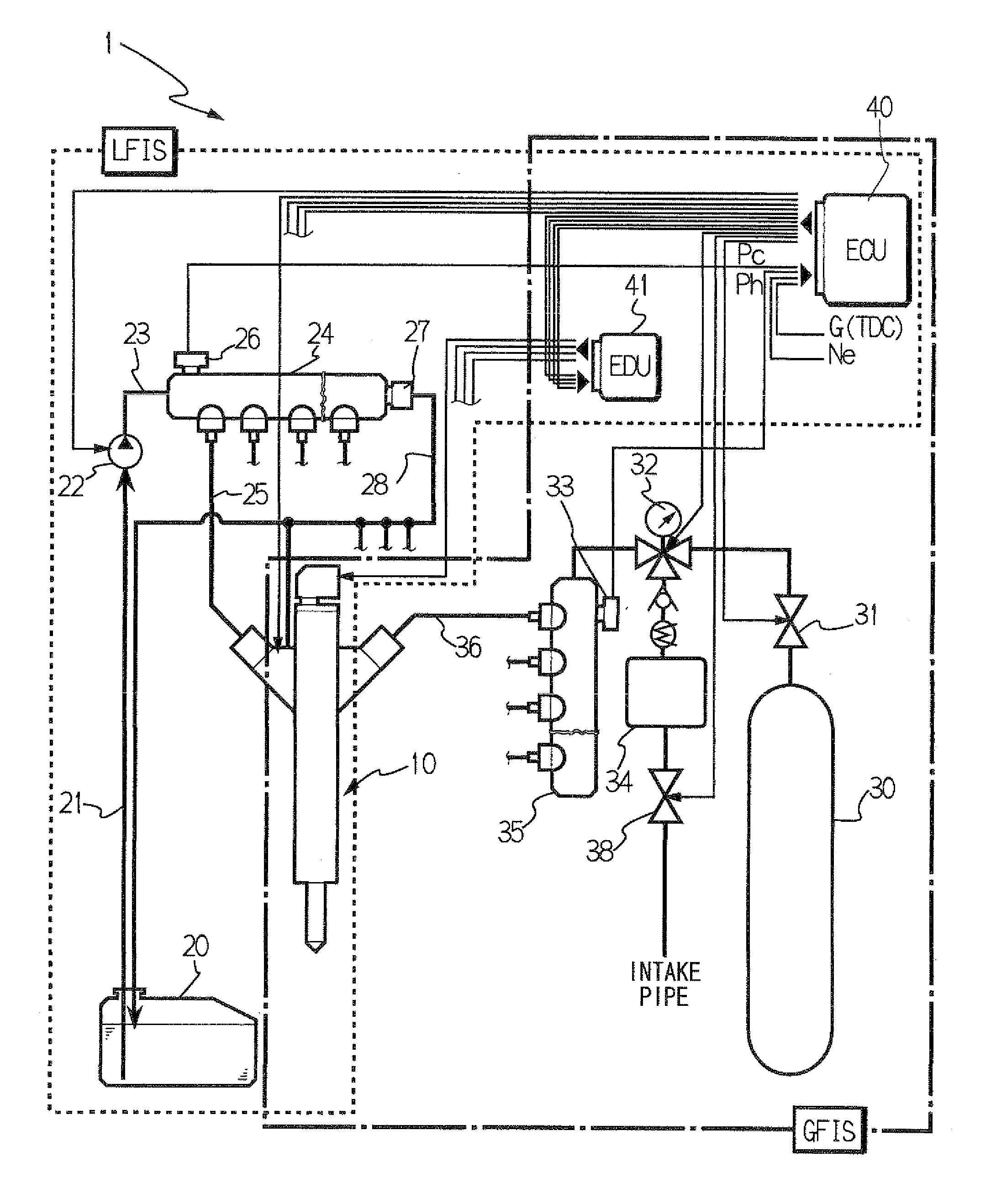
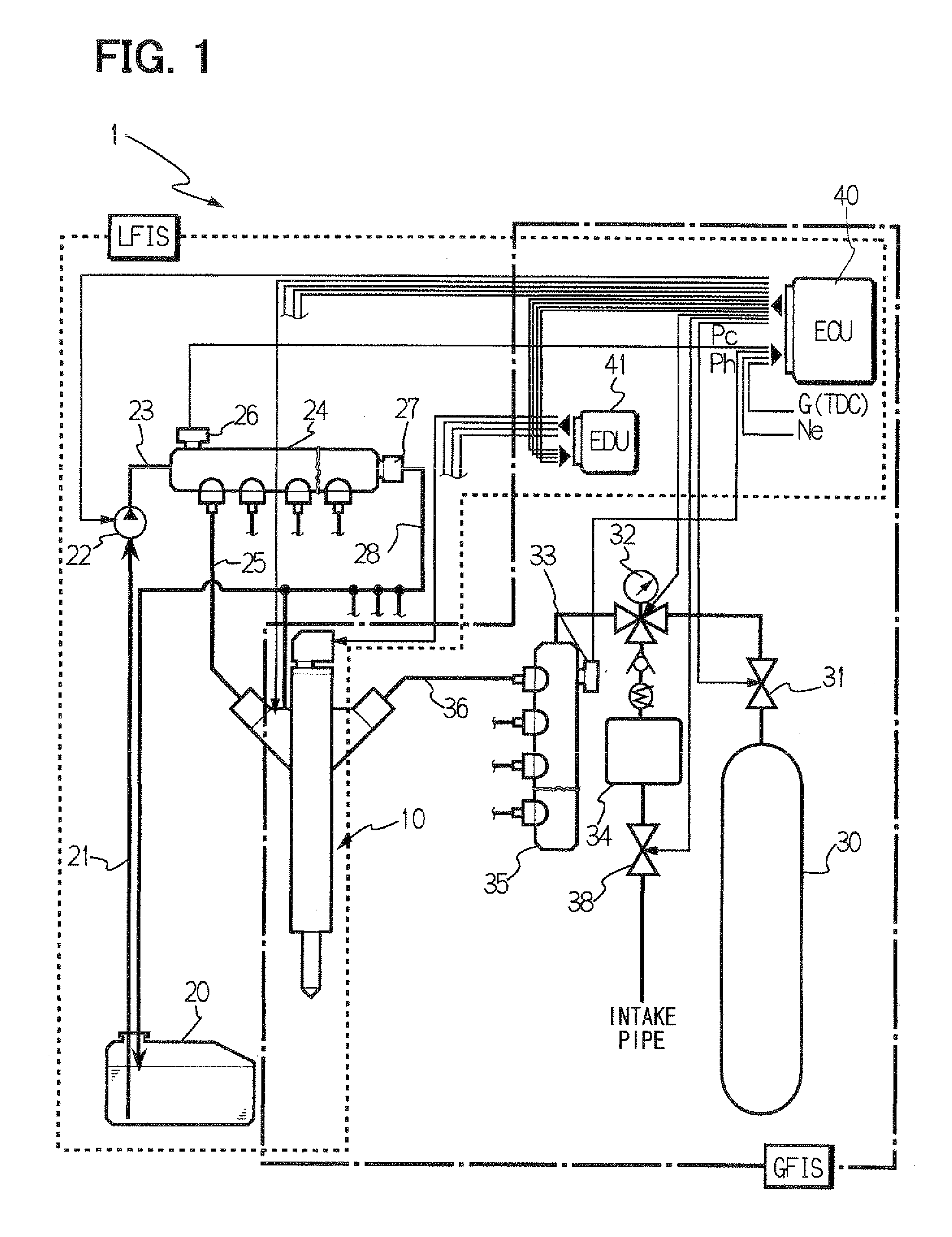
The technology disclosed in JP-A-2003-232234, however, requires high-pressure gaseous fuel supply means (fuel injector for high-pressure gaseous fuel) and high-pressure liquid fuel supply means (fuel injector for high-pressure liquid fuel), possibly leading to complexity, large sizing, and high-costs of the fuel injection device.
In addition, it is extremely difficult to mount the fuel injector to each cylinder and therefore, as shown in JP-A-2003-232234, the multiple fuel injectors are required to be arranged in an intake manifold, estimating that it is difficult to apply this fuel injection device to a direct-injection type engine for injecting fuel directly into an engine cylinder Further, in a case where a remaining quantity of the liquefied petroleum gas is reduced, misfire may occur due to lack of the high-pressure gaseous fuel.
In such a construction, the fuel injection device is sized to be large and therefore, it may be difficult to apply the device to a direct-injection type engine in which the fuel injector is mounted to each cylinder.
However, a detailed structure of the fuel injector is not clear and further, such a construction requires supply fuel switching means in addition to the fuel injector.
Therefore, the construction becomes complicated, possibly leading to large sizing and high costs of the device.
Therefore, the structure of the fuel injector is extremely complicated and particularly, the double-needle valve structure requires an extremely high processing accuracy, possibly leading to high costs of the fuel injector.

Method used


Image

  • Fuel injector and fuel injection device having same
  • Fuel injector and fuel injection device having same
  • Fuel injector and fuel injection device having same

Examples


second embodiment

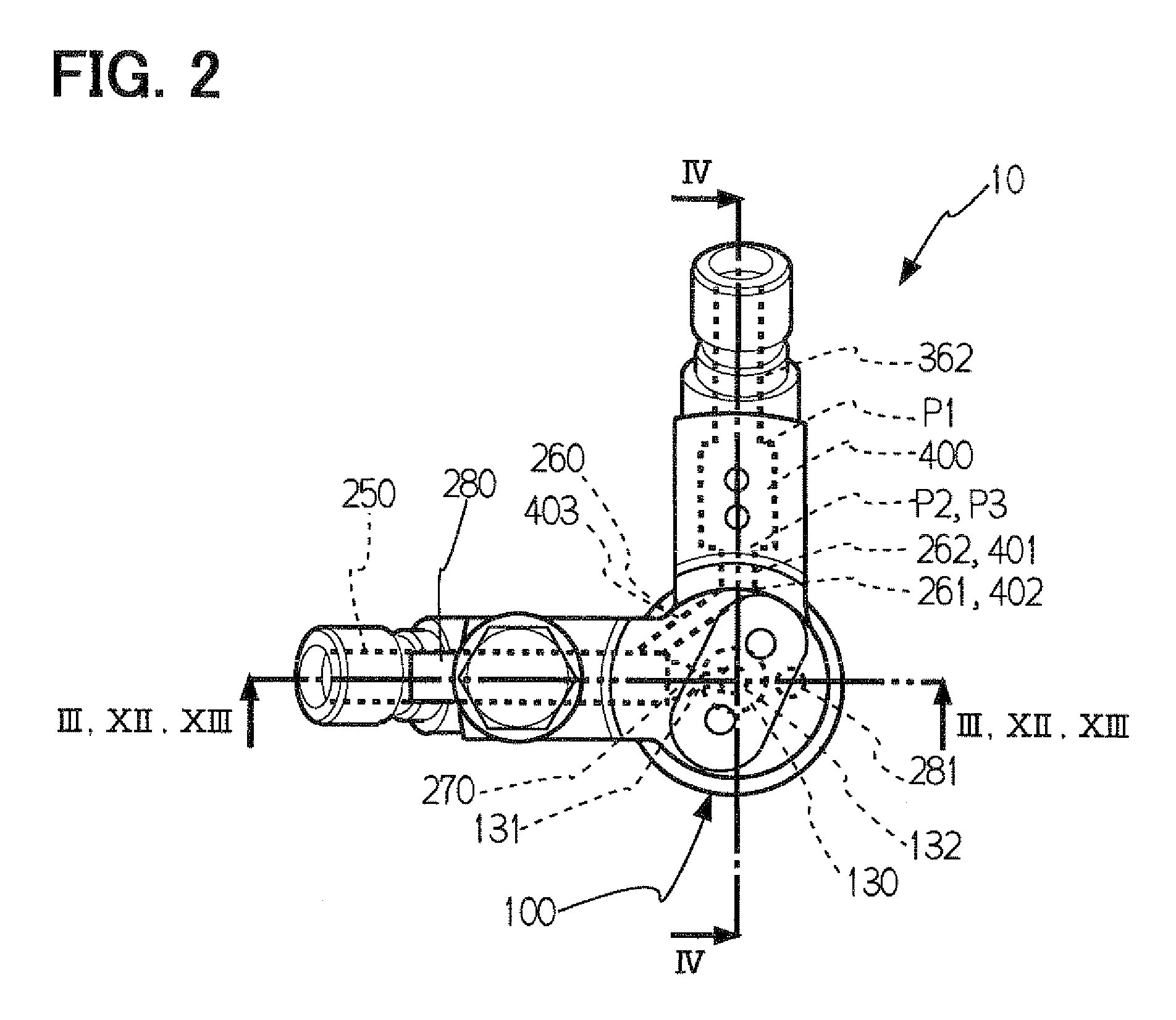
[0057]FIG. 12 to FIG. 14C each shows a fuel injection valve 10a using a passage switching valve 400a according to a second embodiment. Components substantially identical to those in the above embodiment are referred to as identical numerals and description thereof is omitted. FIGS. 12 and 13 are longitudinal cross sections each showing the fuel injection valve 10a according to the present embodiment. FIG. 14A is a schematic diagram showing the flow passage switching valve 400a according to the present embodiment. FIG. 14B is a partial cross section showing the flow passage switching valve 400a at a switching valve position 1. FIG. 14C is a partial cross section showing the flow passage switching valve 400a at a switching valve position 2.

[0058]The present embodiment substantially differs in the following construction from the above first embodiment. A two-position and four-way valve shown in FIG. 14A is used as the flow passage switching valve 400a. A high-pressure GF passage (GF in...


PUM


Abstract

A fuel injector is configured to inject gaseous fuel into a combustion chamber of an engine by using liquid fuel as a pressure transmission medium to open and close a nozzle hole. A nozzle portion has a fuel chamber and a tip end, which defines the nozzle hole. A first passage is configured to communicate the fuel chamber with a gaseous fuel passage to introduce gaseous fuel. A second passage is configured to communicate the fuel chamber with a liquid fuel passage to introduce liquid fuel. A passage switching valve is configured to switch the first passage and the second passage.

Description

CROSS REFERENCE TO RELATED APPLICATIONS[0001]This application is based on and incorporates herein by reference Japanese Patent Application No. 2007-314267 filed on Dec. 5, 2007.FIELD OF THE INVENTION[0002]The present invention relates to a fuel injector for injecting gaseous fuel into a cylinder in an internal combustion engine. The present invention further relates to a fuel injection device having the fuel injector.BACKGROUND OF THE INVENTION[0003]In development of a next-generation automobile, greater importance is given to reduction in environmentally hazardous substances (NOx, CO2, PM or the like) in combustion exhaust gases, but the combustion dependent on the conventional fossil liquid fuel has a limitation to the reduction. Therefore, as alternative fuel to the fossil liquid fuel, development of a gaseous fuel engine using gaseous fuel such as natural gas (LNG and CNG), petroleum gas (LPG) or hydrogen gas, which is expected to have a higher combustion efficiency, is in progr...

Claims


Application Information

Patent Timeline
IPC IPC(8): F02D41/30
CPCF02B1/12F02D19/0631F02D19/105F02D41/0025F02D41/3047F02D19/0694Y02T10/36Y02T10/44F02D19/061F02D19/0676F02D41/402Y02T10/30Y02T10/40
Inventor MASHIDA, MAKOTOKATO, MASAAKIFUNAL, KENJI
Owner DENSO CORP
Learn More