Wheel motor cooling

a technology for wheels and motors, applied in the direction of axially engaging brakes, brake types, braking elements, etc., can solve the problems of adversely affecting the cooling of wheels, brakes and motors after, and achieve the effects of reducing heat flow, increasing space requirements, and adding weigh

Inactive Publication Date: 2009-06-18
BOREALIS TECH LTD
View PDF5 Cites 40 Cited by
  • Summary
  • Abstract
  • Description
  • Claims
  • Application Information

AI Technical Summary

Benefits of technology

[0015]A technical advantage of this approach is that any reduced heat flow that comes about as a result of a motor being located adjacent to the wheel is overcome by running the disengaged motor as a fan cooler. This is achieved without additional added weight or an increased space requirement in the under-carriage bay.
[0016]A further technical advantage of this approach is that with the cooling means in operation, the brake-cooling rate will be considerably increased and the turn-round time will be reduced.
[0017]A further technical advantage is that the peak temperatures of the tire beads and hydraulic fluid will be reduced below critical values.

Problems solved by technology

However, a problem with large aircraft is how to dissipate heat generated by braking, and having additional hardware in the main gear may adversely impact the cooling of the wheels, brakes and motors after a landing event.
However, this magnetic field configuration induces substantial rotor currents in the rotor windings, and the currents produce induction based torque to rotate the rotor.

Method used


Image

  • Wheel motor cooling
  • Wheel motor cooling

Examples


first embodiment

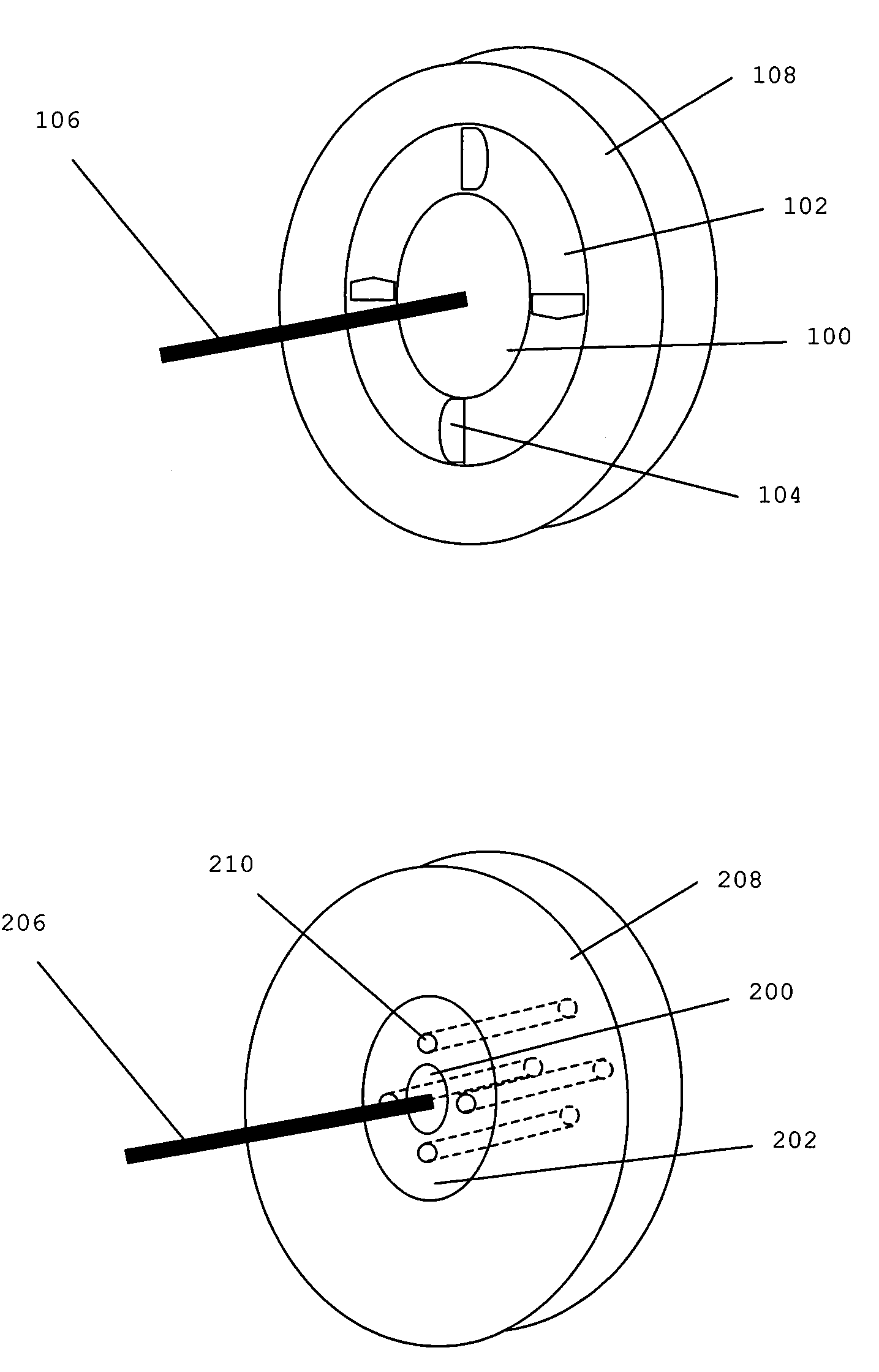
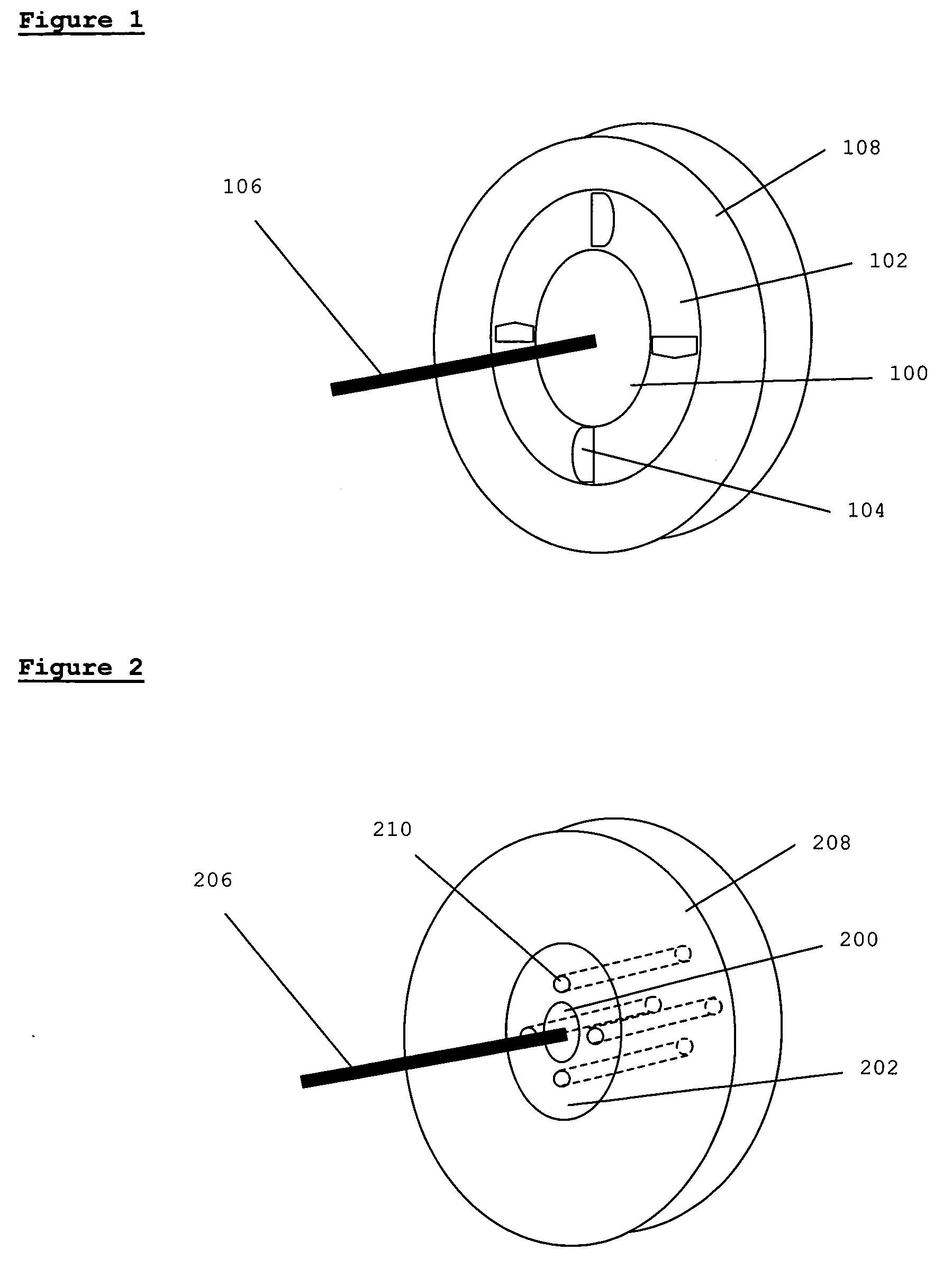
[0024]In the present invention, shown in FIG. 1, said drive means comprises a rotor 102 and a stator 100, mounted on undercarriage wheel 108 and rotationally mounted on axle 106. When said rotor is spun, cooling automatically occurs. Said rotor may be shaped like a fan with fan blades 104 (thus having an integral fan), such that air is circulated near said brakes. Alternatively a fan may be mounted on said rotor. Alternatively or additionally, said rotor may comprise holes or tunnels 210 as shown in FIG. 2, such that air from a cooler location, such as the atmosphere adjacent any outer face of the undercarriage assembly, is brought close to said brakes and circulated around said brakes when said rotor spins. FIG. 2 also shows stator 200 and rotor 202 mounted on undercarriage wheel 208 and axle 206. Furthermore, air pipes or heat pipes may carry air from a cooler location such as an air conditioning unit or other cool location, and bring said air close to said brakes in order that mo...

second embodiment

[0026]Said rotor may be disengaged from said wheel for spinning and the apparatus may further comprise engagement / disengagement means for this purpose, as well as sensing means and control means for spinning the rotor as described in the second embodiment below.

[0027]The figures are given as examples only and are not intended to be limiting. It will be readily understood that many other arrangements and configurations will be possible that will be covered by the scope of this patent, for example, a rotor inside a stator, multiple stators or rotors, eccentric rotors, etc.

[0028]The apparatus may further comprise gears or gear trains as known in the art, or other means for modifying or adapting the speed and / or torque of the drive means with respect to the wheel or cooling means. This includes the use of gears or gear trains, torque converters, planetary gear transmissions, cycloidal reducers, clutches and other known speed and torque transmission means. Said gear, gear train or other ...


PUM


Abstract

The present invention provides a means for cooling the brakes of under-carriage wheels by disengaging and spinning the motor used to provide traction on landing, thereby providing fan cooling of the brakes.

Description

CROSS-REFERENCE TO RELATED APPLICATIONS[0001]This patent application claims the benefit of U.S. provisional patent application No. 61 / 008,283 filed 18 Dec. 2007 which application is included herein in its entirety by reference.BACKGROUND OF THE INVENTION[0002]Methods and apparatus for cooling vehicle motors are disclosed in the art.[0003]WO 2007107489 to Moreau et. al. discloses a fan propeller for cooling a vehicle engine or motor, placed in front of or behind the engine cooling radiator. The invention is concerned with reducing weight and improving performance by having specific thickness profile. To this end the fan propeller comprises a hub and blades extending radially outwards from the hub, the blades having a flattened cross-section with an aircraft wing profile including a leading edge and a trailing edge between which is defined a chord. The blade has a relative thickness up to a maximum value (Emax) in the first quarter of the chord length starting from the leading edge, t...

Claims


Application Information

Patent Timeline
Patent Type & Authority Applications(United States)
IPC IPC(8): F16D55/02
CPCF16D65/847F16D65/827
Inventor COX, ISAIAH WATAS
Owner BOREALIS TECH LTD
Why Eureka
Try Eureka