Micro actuator

Active Publication Date: 2009-06-18
THK CO LTD
View PDF2 Cites 20 Cited by
  • Summary
  • Abstract
  • Description
  • Claims
  • Application Information

AI Technical Summary

Benefits of technology

[0007]The present invention has been made in view of the above-mentioned problems, and therefore has an object to provide a micro actuator capable of being formed in compact as a whole, such as 10 mm in diameter, by diminishing a difference between a stroke distance of a moving member and an overall length and by reducing a sectional area taken in a direction orthogonal to a stroke direction.
[0008]Another object of the present invention is to provide a micro actuator which includes a smaller number of components, and can be assembled easily.
[0011]In the micro actuator of the present invention, constructed as described above, the end openings of the spline shaft are stopped by the pair of end caps, whereby the magnet rod is supported in the hollow part of the spline shaft, and the linear motor as the drive mechanism is completely accommodated in the spline shaft as the guide mechanism. As a result, it is possible to diminish the difference between the stroke length of the spline nut and the overall length of the actuator. Further, due to the use of a so-called rod type linear motor, in which the forcer is loosely fit-engaged with the periphery of the magnet rod, a sufficient thrust can be obtained even if the forcer is downsized, making it possible for the diameter of the spline shaft, which accommodates the forcer in the hollow part thereof, to be set small. As a result, according to the present invention, it is possible to obtain a linear actuator markedly downsized, that is, a micro actuator.
[0012]Further, as described above, in the micro actuator of the present invention, the magnet rod constituting the linear motor is fixed to the spline shaft by a pair of end caps, and the assembly operation is substantially completed solely by connecting the forcer with the spline nut, so the number of components is relatively small, and the assembly can be conducted easily, thus allowing production at a lower cost.

Problems solved by technology

While there are various combinations of the drive mechanism and the guide mechanism according to the requisite thrust for the moving member, load bearing capacity, moving speed, precision, etc., simply combining an arbitrary drive mechanism and guide mechanism results in a linear actuator of a rather large size, which leads to a rather poor usability.

Method used


Image

  • Micro actuator
  • Micro actuator
  • Micro actuator

Examples


first embodiment

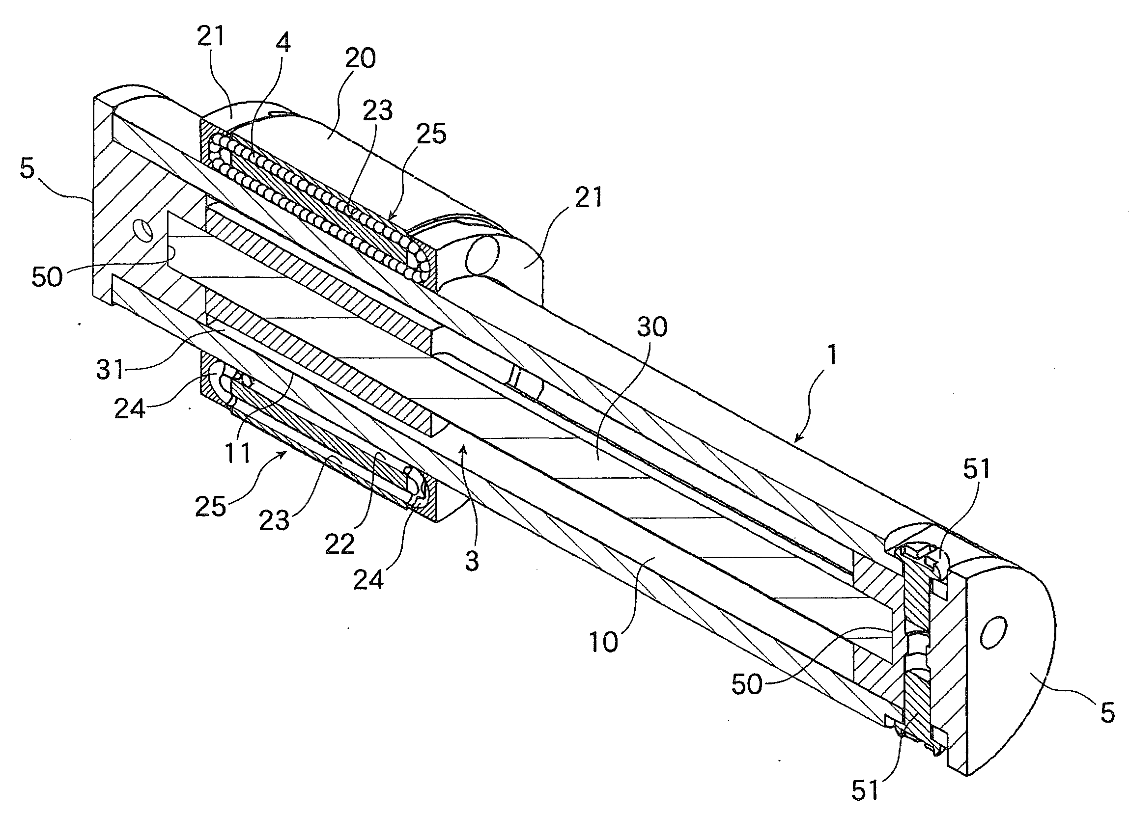
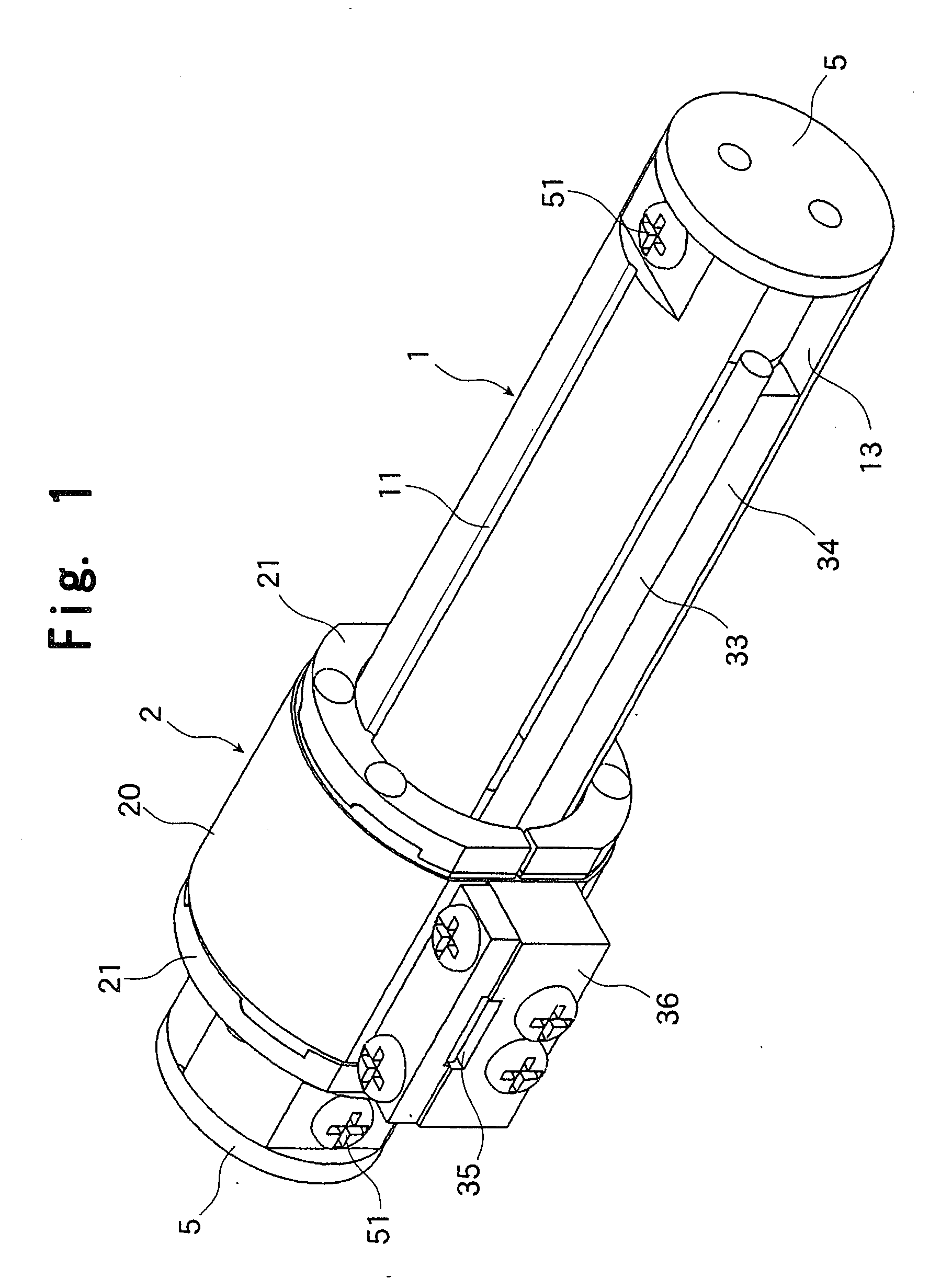
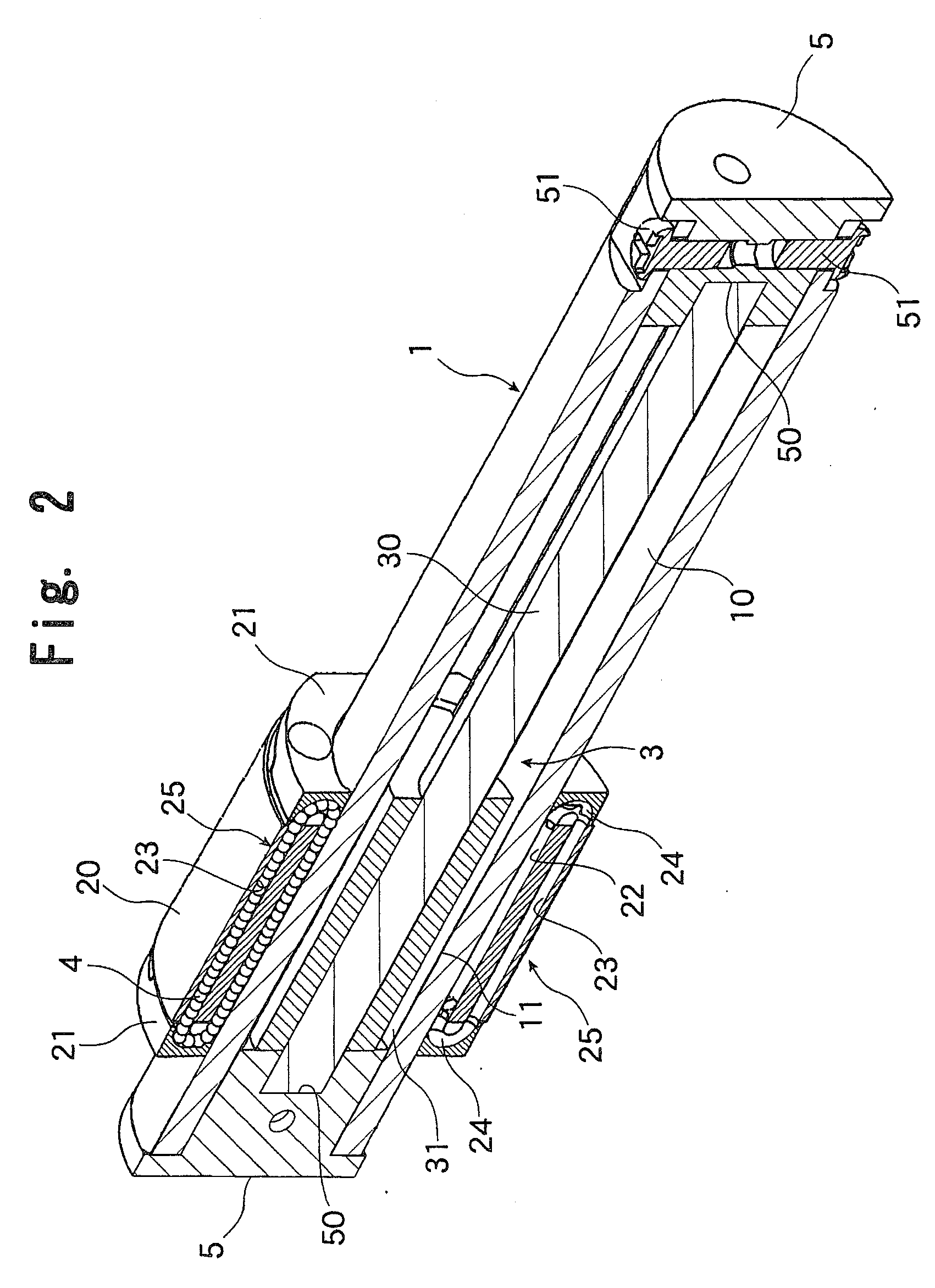
[0022]FIGS. 1 through 4 show a micro actuator according to the present invention. FIG. 1 is a general perspective view, FIG. 2 is a vertically cutaway longitudinal perspective view, FIG. 3 is a horizontally cutaway longitudinal perspective view, and FIG. 4 is a perspective view cut away perpendicularly to the longitudinal direction at the center of a spline nut described below. This micro actuator is equipped with a spline shaft 1 having a hollow part 10 and formed in a substantially cylindrical configuration, and a spline nut 2 fit-engaged with the outer side of the spline shaft 1 through the intermediation of a large number of balls, and is capable of reciprocating the spline nut 2 in the axial direction of the spline shaft 1 by utilizing thrust generated by a linear motor 3 accommodated in the hollow part 10 of the spline shaft 1.

[0023]The spline shaft 1 has the hollow part 10 and is formed in a cylindrical configuration, with the outer peripheral surface thereof having two ball ...

second embodiment

[0036]FIGS. 5 and 6 show a micro actuator according to the present invention, in which, as stated above, only one slit opening 14 is formed for the spline shaft 1. FIG. 5 is a general perspective view, and FIG. 6 is a general perspective view as seen from the opposite side.

[0037]In FIG. 5, the slit opening 14 extending in the axial direction is provided at one position in the outer peripheral surface of the spline shaft 1, and the spline nut 2 is connected with the forcer 31 constituting the linear motor 3 through the slit opening 14.

[0038]Further, as shown in FIG. 6, a flat surface 60 is formed on the outer peripheral surface of the spline shaft at position out of phase with respect to the slit opening by 180°, and a tape-like linear scale 61 is attached to the flat surface 60. As in the first embodiment, the linear scale 61 is formed as a magnet scale. A reading head (not shown) is fixed to the spline nut 2 at a position opposed to the linear scale 61; when the spline nut 2 moves ...

third embodiment

[0041]Next, FIG. 7 shows a micro actuator according to the present invention.

[0042]In the micro actuator of the third embodiment, in order to enhance the thrust exerted by the linear motor 3, a plurality of sets of exciting coils, of which each three exciting coils of the three phases constitutes one set, are mounted on a forcer 37 loosely fit-engaged with the magnet rod 30. Thus, the forcer 37 is formed longer in the axial direction of the magnet rod 30 as compared with the forcer 31 of the second embodiment. Further, in order to reliably support the elongated forcer 37, a pair of spline nuts 2 are fit-engaged with the spline shaft 1 at an axial interval, with the spline nuts 2 being respectively connected with the longitudinal ends of the forcer 37. That is, the pair of spline nuts 2 are connected to each other through the intermediation of the forcer 37; when the linear motor 3 is driven, the spline shaft 1 retaining the magnet rod 30 moves relative to the spline nuts 2, with the...


PUM


Abstract

Disclosed is a micro actuator capable of being formed in compact as a whole, such as 10 mm in diameter by diminishing a difference between a stroke distance of a moving member and an overall length, and by reducing a sectional area taken in a direction orthogonal to a stroke direction. The micro actuator includes: a spline shaft formed as a cylinder with a hollow part and having an axially extending slit opening; a spline nut fit-engaged with the spline shaft and axially guiding the spline shaft; a pair of end caps fixed to openings at both ends of the spline shaft; a magnet rod supported at both ends within the hollow part of the spline shaft by the end caps; and a forcer loosely fit-engaged with a periphery of the magnet rod within the hollow part of the spline shaft to constitute a linear motor together with the magnet rod and connected with the spline nut through the slit opening.

Description

TECHNICAL FIELD[0001]The present invention relates to an actuator with a built-in driving means, in which a spline shaft and a spline nut can move relative to each other in response to an input signal. In particular, the present invention relates to a micro actuator capable of being downsized into about 10 mm in diameter, and being used for various industrial appliances.BACKGROUND ART[0002]Hitherto, a linear actuator, which converts an electric input signal into a linear movement of a moving member and outputs the same, mainly includes a guide mechanism for linearly guiding the moving member while bearing an external force, and a drive mechanism for causing the moving member to advance and retreat along the guide mechanism. There are various known examples of the drive mechanism, including a linear actuator which uses a hydraulic cylinder or an air cylinder as the drive source, and which transmits a linear reciprocating motion of a piston as it is to the moving member, and an actuat...

Claims


Application Information

Patent Timeline
IPC IPC(8): H02K5/04
CPCH02K41/03
Inventor KIMURA, YOSHIHIROASO, TOSHIYUKITANAKA, YOSHINOBUMICHIOKA, HIDEKAZUIIZUMI, MAKOTO
Owner THK CO LTD
Why Eureka
Try Eureka