
Apparatus, method and system for control of ac/ac conversion

a technology of ac/ac conversion and control apparatus, applied in the direction of electric variable regulation, process and machine control, instruments, etc., can solve the problems of harmonic distortion and/or phase distortion, high production cost, and high ups. large and/or expensive for many applications

Active Publication Date: 2009-06-18
YAIRONIT LTD
View PDF12 Cites 38 Cited by
  • Summary
  • Abstract
  • Description
  • Claims
  • Application Information

AI Technical Summary

Benefits of technology

[0015]Embodiments of the present invention may include systems using apparatuses or methods described herein. Systems in accordance with the present invention may include the apparatus for regulating or controlling voltage an electrical appliance, wherein the apparatus is configured to receive an input voltage and provide a stabilized output voltage to the appliance. In some systems, the apparatus of the present invention may be used for correcting power factor of the output voltage. In some embodim

Problems solved by technology

Known devices and methods for stabilizing AC output voltage may typically require conversion to direct current (DC) and then back to AC, which may result in inefficiency and high production costs.
Yet other systems may use or include an uninterruptible power supply (UPS), however, the UPS may be too large and / or expensive for many applications that may benefit from stabilized or regulated AC output voltage.
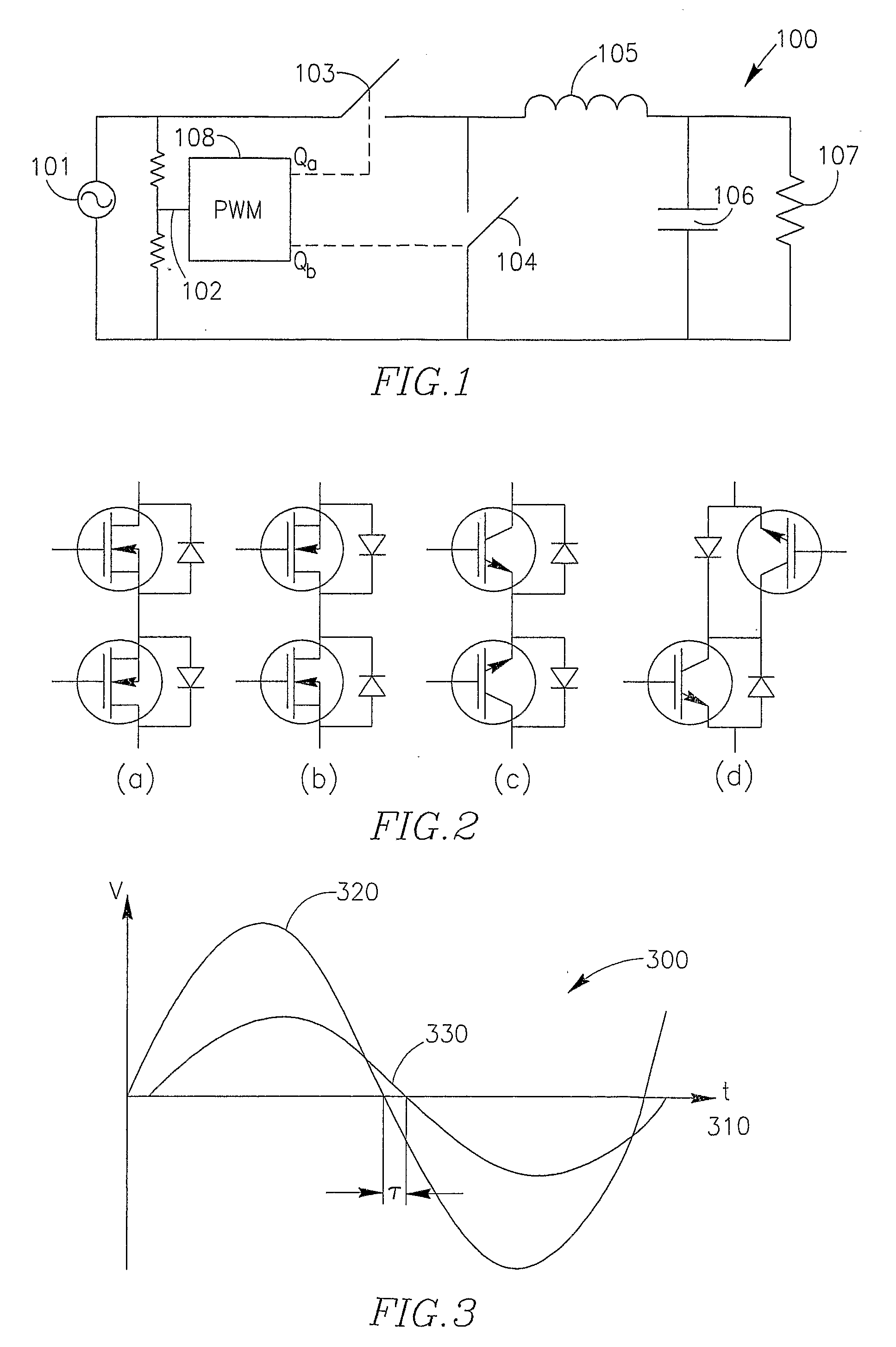
In the configuration of FIG. 1, due to the output filter constructed using inductor 105 and capacitor 106, the output voltage will be delayed relative to the input voltage, and therefore, the output voltage may be out of phase with the input voltage signal, thereby producing harmonic distortion and / or phase distortion.
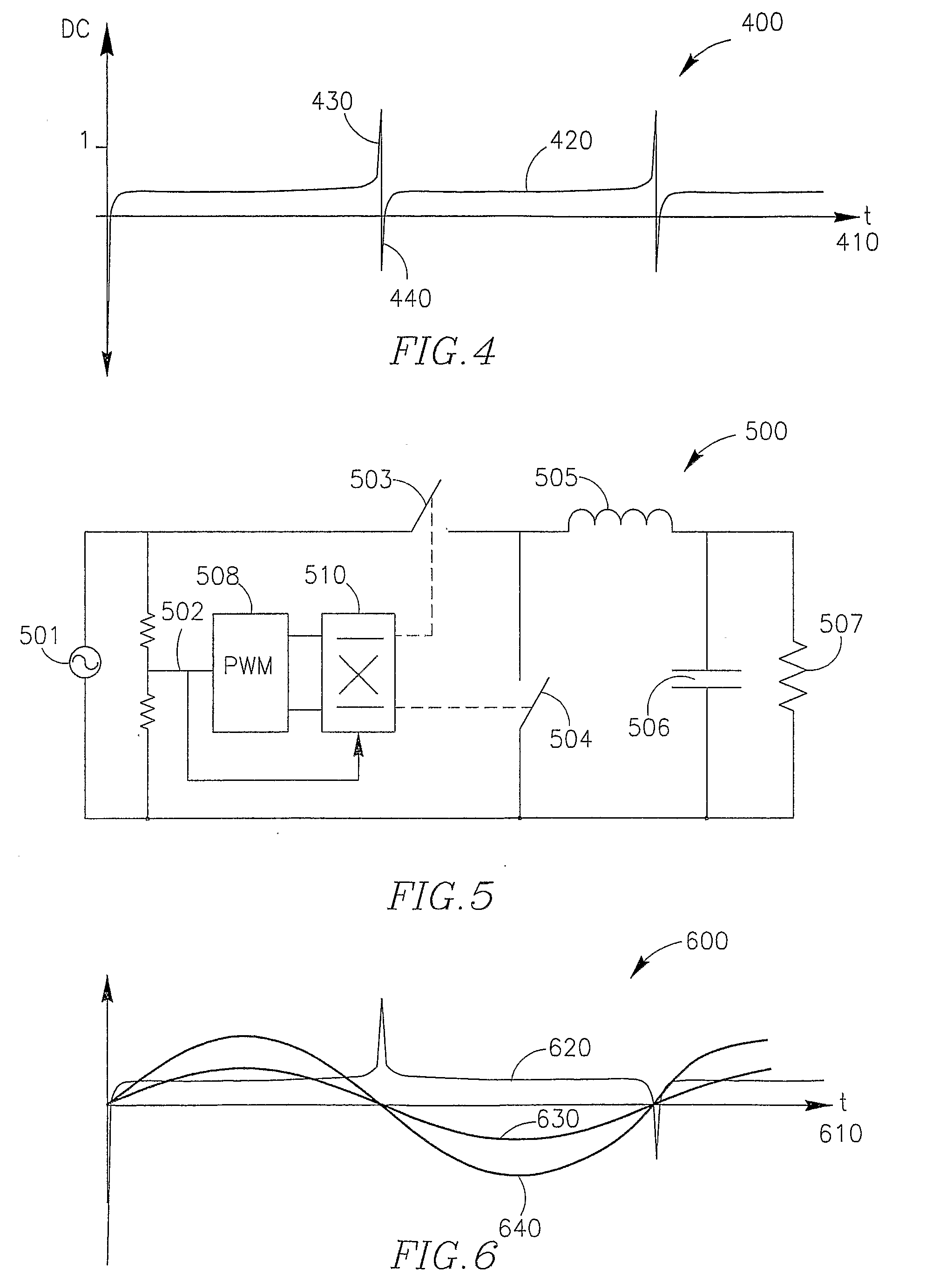
Closing the control loop for zero delay output voltage with respect to input voltage, however, may result in the duty cycle demand as shown in FIG. 4.
In addition, in real-world applications, it is difficult if not impractical for the control loop to handle an instantaneous change from positively infinite required duty cycle to a negatively infinite required duty cycle, or, for example, 100% duty cycle to 0% duty cycle.
Accordingly, the output voltage may contain errors and total harmonic distortion (THD) may result.

Method used


Image

  • Apparatus, method and system for control of ac/ac conversion
  • Apparatus, method and system for control of ac/ac conversion
  • Apparatus, method and system for control of ac/ac conversion

Examples


Embodiment Construction

[0032]In the following detailed description, numerous specific details are set forth in order to provide a thorough understanding of the invention. However, it will be understood by those skilled in the art that the present invention may be practiced without these specific details. In other instances, well-known methods, procedures, and components have not been described in detail so as not to obscure the present invention.

[0033]Embodiments of the invention may employ a method and device for controlling a pulse width modulator (PWM) converter for direct AC / AC conversion and / or AC voltage regulation. According to some embodiments of the invention, an output voltage may be provided, independent of the input voltage quality, thereby avoiding or minimizing power company irregularities, brownouts and the like. Embodiments of the present invention may be useful, for example, for use in connection with motors and motored devices or other applications.

[0034]Embodiments of the present invent...


PUM


Abstract

A method, system and apparatus for controlling a pulse width modulator (PMW) converter for direct AC / AC conversion and / or AC voltage regulation. According to some embodiments of the invention, an output voltage may be provided, independent of the input voltage quality, thereby avoiding or minimizing power company irregularities, brownouts and the like. Embodiments of the present invention may be useful, for example, for use in connection with motors and motored devices or other applications.

Description

FIELD OF THE INTENTION[0001]The field of this invention is generally power conversion, and more specifically, power conversion and / or voltage regulation for AC / AC applications.BACKGROUND OF THE INVENTION[0002]In some alternating current (AC) electrical systems it may be beneficial to provide for stabilization of the output voltage. Known devices and methods for stabilizing AC output voltage may typically require conversion to direct current (DC) and then back to AC, which may result in inefficiency and high production costs. Other devices may use variacs, electromechanical devices, and / or components with ferro-resonance characteristics. Yet other systems may use or include an uninterruptible power supply (UPS), however, the UPS may be too large and / or expensive for many applications that may benefit from stabilized or regulated AC output voltage. Accordingly, there is a need for an efficient and inexpensive method and device for AC voltage stabilization.[0003]FIG. 1 illustrates a st...

Claims


Application Information

Patent Timeline
IPC IPC(8): G05F1/00
CPCH02M5/293H02P27/00H02M2005/2932H05B41/3924G05F5/00H05B39/048H02M5/2932
Inventor ZILBERBERG, OFER
Owner YAIRONIT LTD
Learn More