Obstacle Detection System and Obstacle Detection Method Thereof

a detection system and obstacle technology, applied in the direction of resistance/reactance/impedence, pulse technique, instruments, etc., can solve the problems of significant limiting factors of operation relative to productivity, operation errors can occur in static capacitance detection circuits, and the above-described type of obstruction detection systems are accompanied by a number of problems, so as to improve productivity and simplify the overall configuration of the product , the effect of reducing manufacturing costs

Active Publication Date: 2009-06-18
AUTOTECH
View PDF2 Cites 35 Cited by
  • Summary
  • Abstract
  • Description
  • Claims
  • Application Information

AI Technical Summary

Benefits of technology

[0035]A static capacitance detection circuit to be used in an obstacle detection system according to the present invention as defined above can be manufactured without requiring any complex frequency tuning process so that such an obstacle detection system can realize a remarkably improved productivity. In other words, such an obstacle detection system provides an advantage that the oscillation frequencies of the RF oscillators can be tuned by controlling the phase lock loop after manufacturing the static capacitance detection circuit.
[0036]Additionally, an obstacle detection system according to the present invention as defined above can be formed by using only RF oscillators, eliminating the use of a local oscillator and a mixer so that the overall configuration of the product is simplified and the manufacturing cost can be reduced. Still additionally, since the phase lock loop can constantly maintain the oscillation frequencies of the RF oscillators to predetermined respective values so that the product is prevented from giving rise to operation errors and the reliability of the product is remarkably improved. Additionally, the reliability of product is further improved because it can accurately detect an obstacle if dead points are produced in the sensor strip of the obstacle detection system.

Problems solved by technology

Obstacle detection systems of the above-described type are accompanied by a number of problems as listed below.
Firstly, while the oscillation frequency of the RF oscillator 42 and that of the local oscillator 40 are determined by way of a frequency tuning operation in the process of manufacturing the static capacitance detection circuit 16 but the accuracy of such a tuning operation depends on the experience of the operator and involves trial and error so that such an operation constitutes a significant limiting factor relative to productivity.
Then, operation errors can take place to the static capacitance detection circuit 12.
If an operation error takes place for such reasons, it is highly difficult for the user to tune the oscillation frequencies and hence he or she will have to buy a new one.
Thirdly, there is a problem that there exist cyclic dead points in the operating area of a static capacitance detection circuit where any approaching obstacle cannot be detected.
However, when the oscillation frequency is lowered, the oscillation frequency changes only to a small extent when an obstacle approaches the sensor strip so that the static capacitance detection circuit 12 shows a poor sensitivity.
Then, it may sometime not properly detect an obstacle.
When, on the other hand, the oscillation frequency is raised too much, the manufacturing cost will rise and design difficulties will become enormous among other problems.

Method used


Image

  • Obstacle Detection System and Obstacle Detection Method Thereof
  • Obstacle Detection System and Obstacle Detection Method Thereof
  • Obstacle Detection System and Obstacle Detection Method Thereof

Examples


first embodiment

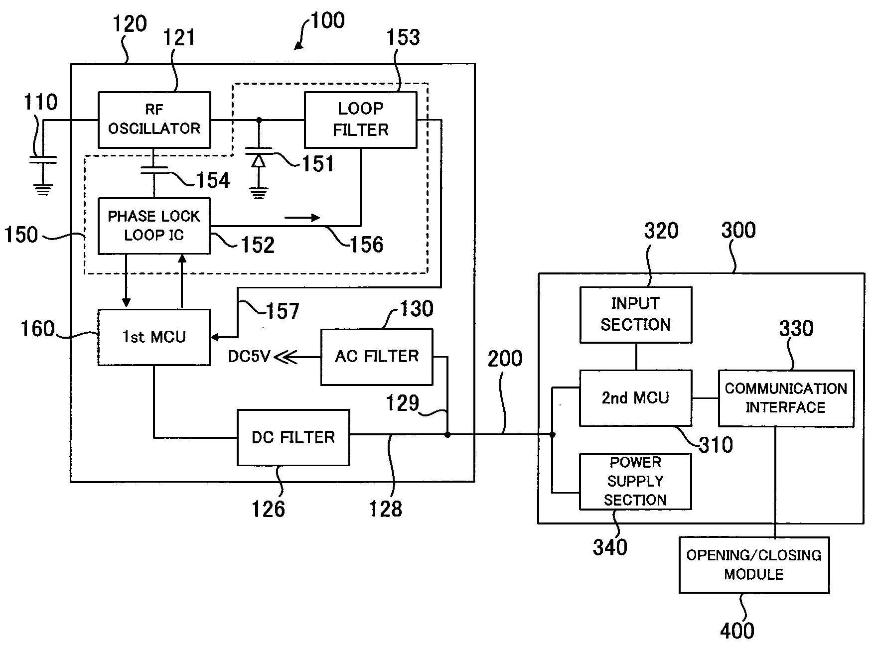
[0045]FIG. 4 is a circuit block diagram of the static capacitance detection system according to the first embodiment of the present invention. The illustrated static capacitance detection system includes a static capacitance detection module 100, a control module 300 and a transmission line 200 for transmitting signals between the static capacitance detection module 100 and the control module 300.

[0046]The static capacitance detection module 100 by turn includes a sensor strip 110 for detecting a static capacitance and a static capacitance detection circuit 120 that detects a change in the static capacitance of the sensor strip 110 and outputs a signal corresponding to the change.

[0047]The sensor strip 110 is formed by inserting a thin strip-shaped n conductor into a highly flexible insulator typically made of rubber like known popular sensor strips, while the static capacitance detection circuit 120 is formed on a small printed circuit board (PCB) and contained in an end part of th...

second embodiment

[0078]The first embodiment of obstacle detection system and obstacle detection method is designed to constantly maintain the oscillation frequency of the RF oscillator to a predetermined level by utilizing a phase lock loop. However, the first embodiment is not free from dead points that appear in the sensor strip at regular intervals like known obstacle detection systems.

[0079]This second embodiment of optical detection system is designed to dissolve the poor sensitivity problem relative to dead points and characterized in that the RF oscillator 121 that now includes a frequency changing section 17C as shown in FIG. 5 is caused to oscillate at a plurality of frequencies sequentially and repeatedly.

[0080]For the purpose of simplicity, the components of the second embodiment that are same as those of the first embodiment will not he described in the following description of the second embodiment.

[0081]The frequency changing section 170 is connected at one of the opposite ends thereof...

third embodiment

[0100]The first MCU 160 periodically controlled the frequency changing section 170 so as to make the RF oscillator 121 alternately oscillate at the first frequency and at the second frequency in the above-described second embodiment.

[0101]The obstacle detection system of the third embodiment differs from the second embodiment and is characterized in that it includes two RF oscillators including a first RF oscillator 121 that oscillates at a first frequency and a second RF scanner 181 that oscillates at a second frequency as shown in FIG. 7.

[0102]Like the first and second embodiments, the oscillation detection system of the third embodiment includes a static capacitance detection module 100, a control module 300 and a transmission line 200 for transmitting signals between the static capacitance detection module 100 and the control module 300. The static capacitance detection module 100 by turn includes a sensor strip 110 and a static capacitance detection circuit 120 that is connecte...


PUM


Abstract

An obstacle detection system includes a static capacitance detection module including a sensor strip for detecting a static capacitance, an RF oscillator connected to the sensor strip, a phase lock loop section for maintaining the oscillation frequency of the RF oscillator to a selected value and a first MCU for controlling the operation of the phase lock loop section, a control module including a second MCU for remotely controlling the first MCU of the static capacitance detection module and a transmission line for connecting the static capacitance detection module and the control module and transmitting the information acquired by the first MCU so as to be transmitted to the control module, a control signal to be transmitted from the second MCU to the first MCU and drive power of the static capacitance detection module.

Description

CROSS REFERENCE TO RELATED APPLICATION[0001]This patent application is based upon and claims the benefit of priority from prior Korean Patent Application No. 10-2007-132448, filed Dec. 17, 2007, the entire contents of which are incorporated herein by reference.BACKGROUND OF THE INVENTION[0002]1. Field of the Invention[0003]The present invention relates to an obstacle detection system for detecting an obstacle by utilizing a change in the static capacitance and a method thereof. More particularly, the present invention relates to an obstacle detection system and a detection method thereof that can provide an improved detection accuracy and an improved reliability by utilizing a phase locked loop.[0004]2. Description of the Related Art[0005]The doors of a vehicle are to be opened and closed directly by hand in the past. However, the number of vehicles having doors that can be opened and closed remotely by operating a button has been and is increasing.[0006]In accordance with such a tr...

Claims


Application Information

Patent Timeline
Patent Type & Authority Applications(United States)
IPC IPC(8): G01R27/26
CPCH03K17/955H03L7/099H03L7/07G01R27/26
Inventor CHO, SEUNG WONJEONG, KWANG SEOK
Owner AUTOTECH
Why Eureka
Try Eureka