Particle detector

a particle detector and detector technology, applied in the field of particle detectors, can solve the problems of difficult to distinguish between noise due to outside light, noise due to lasers, or electric noise, and the shortening of the pulse width of the particle signal,

Inactive Publication Date: 2009-06-18
RION COMPANY
View PDF6 Cites 22 Cited by
  • Summary
  • Abstract
  • Description
  • Claims
  • Application Information

AI Technical Summary

Problems solved by technology

Therefore, the pulse width of the particle signal becomes shorter, which makes it difficult to detect the particles.
However, according to the conventional structure, since the pulse width

Method used


Image

  • Particle detector
  • Particle detector
  • Particle detector

Examples


first embodiment

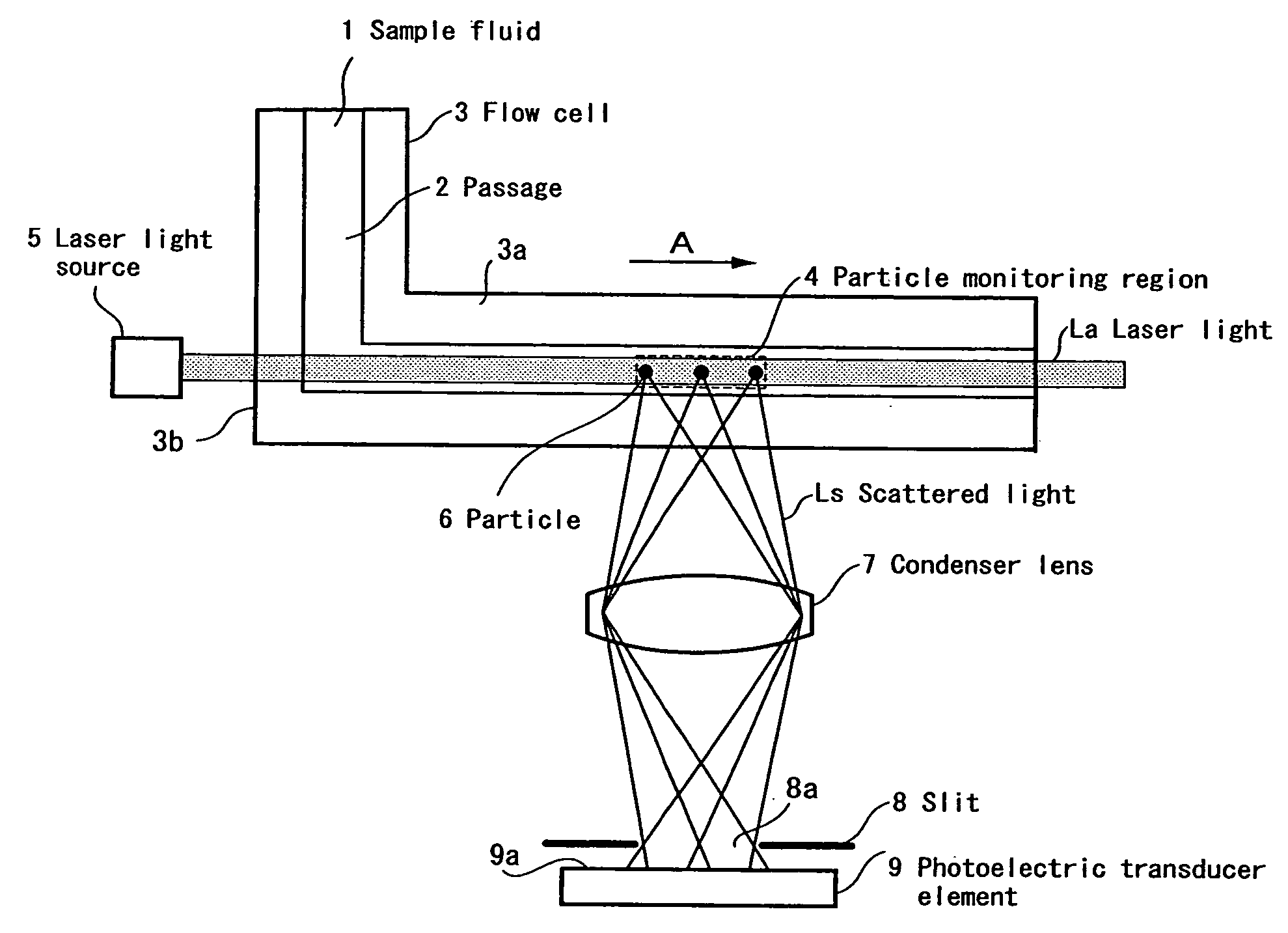
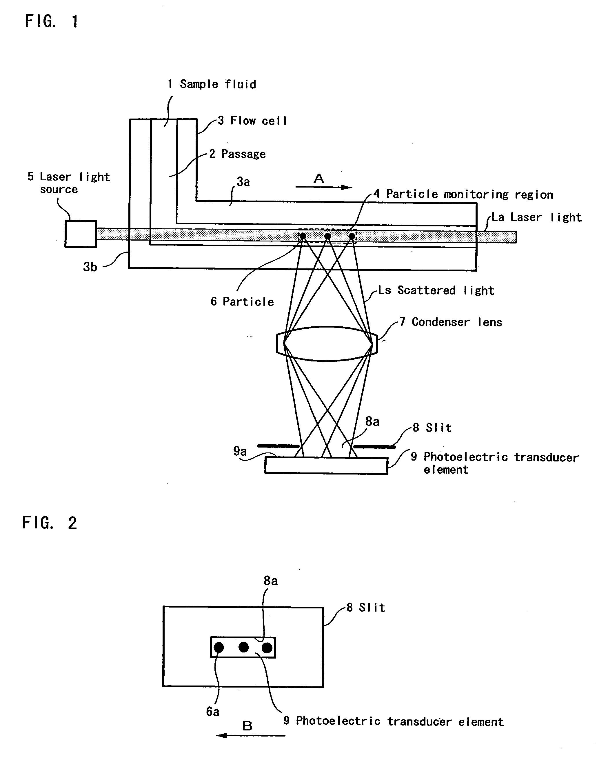
[0023]As shown in FIG. 1, the particle detector of the first embodiment is comprised of a flow cell 3, provided with a passage 2 through which the sample fluid 1 flows, a laser light source 5 for irradiating the passage 2 with laser light La so as to form a particle monitoring region 4, a condenser lens 7 for condensing scattered light Ls generated by particles 6 passing through the particle monitoring region 4, a slit 8 for blocking unwanted light from outside, and a photoelectric transducer element 9 for converting light condensed by the condenser lens 7 into a voltage corresponding to the intensity of the light.

[0024]The flow cell 3 is made of a transparent material, and is provided with a linear passage 3a of a predetermined length. The flow cell 3 is bent as a whole. In addition, the cross section of the flow cell 3 has a rectangular shape, and the whole shape of the flow cell 3 is an L-shaped tube. The reason the flow cell 3 has the linear passage 3a of a predetermined length ...

second embodiment

[0035]Next, as shown in FIG. 5, the particle detector of the second embodiment is comprised of a flow cell 3 provided with a passage 2 through which the sample fluid 1 flows, a laser light source 5 for irradiating the passage 2 with laser light La so as to form a particle monitoring region 4, a concave mirror 20 for condensing scattered light Ls generated by particles 6 passing through the particle monitoring region 4, a slit 8 for intercepting unwanted light from outside, and a photoelectric transducer element 9 for converting light condensed by the concave mirror 20 into a voltage corresponding to the intensity of the light.

[0036]The concave mirror 20 has an optical axis perpendicular to the central axis of the linear passage 3a of the flow cell 3, and condenses scattered light Ls generated by particles 6 irradiated with the laser light La in the particle monitoring region 4. The slit 8 is provided with a slit aperture 8a, and the longitudinal direction of the slit 8a corresponds ...


PUM


Abstract

A particle detector which can detect smaller particles by increasing the pulse width of the particle signal output from a photoelectric transducer element, includes a particle monitoring region formed by irradiating sample fluid with laser light, and light scattered from particles passing through the particle monitoring region is received by a photoelectric transducer element so as to detect a particle. The direction of flow of the sample fluid and the direction of the laser light are arranged parallel to each other. The particle detector may have a condenser lens for condensing the scattered light and a slit provided at a focal point of the condenser lens and extending in a direction parallel to the sample fluid flow. Also, the particle detector may have a condenser circuit for integrating the output signal of the photoelectric transducer element, and a low-pass filter for filtering the output signal of the condenser circuit.

Description

TECHNICAL FIELD[0001]The present invention relates to a particle detector which can detect fine particles contained in sample fluid.BACKGROUND ART[0002]In a conventional particle detector, laser light is directed perpendicularly or at an angle toward sample fluid flowing through a flow cell, and light scattered by fine particles contained in the sample fluid is detected by a photoelectric transducer element (for example, Patent Document 1). In this instance, when particles pass laser light, scattered light is generated. Accordingly, the output signal (particle signal) of the photoelectric transducer element becomes a pulse.[0003]These days, high-density and high-accuracy fine processing is required to manufacture precise electronic devices, and high purity is required with respect to the ultra-pure water or chemical liquid used therein. In order to control such purity, a particle detector is used. As for ultra-pure water, it is necessary to measure and control fine particles whose d...

Claims


Application Information

Patent Timeline
IPC IPC(8): G01N21/53
CPCG01N2015/03G01N15/0205
Inventor MATSUDA, TOMONOBU
Owner RION COMPANY
Why Eureka
Try Eureka