Pump Driving Apparatus

Inactive Publication Date: 2009-06-18
YG K R & D
View PDF6 Cites 3 Cited by
  • Summary
  • Abstract
  • Description
  • Claims
  • Application Information

AI Technical Summary

Benefits of technology

[0014]When the pump driving apparatus according to the present invention is used, a guide tube is provided inside the pump chamber so as to be coaxial with the fixed shaft, wherein ends of the guide tube in the axial direction are fitted to and make sliding contact with a case wall surface that forms the pump chamber and a core-side wall surface of the impeller enclosed inside the pump chamber. This means that when the impeller is rotated to draw in low-pressure liquid in the axial direction into the pump chamber and expel the liquid toward the outer periphery, high-pressure liquid that flows back toward the core from the outer periphery of the pump chamber via a gap between the impeller and the pump case due to the pressure difference in the pump chamber can be effectively blocked by the guide tube. Therefore, it is possible to prevent vigorous collisions between high-pressure liquid that has flowed back in the pump chamber and the low-pressure liquid drawn in at the core due to the pressure difference inside the pump chamber, and therefore pump efficiency can be improved. Also, since it is possible to reduce the gap between the impeller and the pump

Problems solved by technology

Firstly, it is necessary to prevent interference due to insufficient precision in the dimensions of the pump case 62 that is integrally molded.
In addition, centering is difficult for the impeller 59 which is formed by welding together an upper portion, where the radial protruding ribs 67 are formed, and a lower portion, where the coupling magnet 61 is enclosed, which means that it is difficult to manufacture a pump driving apparatus with components that are precisely concentric.
However, a pressure difference is produced inside the pump chamber 58, resu

Method used


Image

  • Pump Driving Apparatus
  • Pump Driving Apparatus
  • Pump Driving Apparatus

Examples


Example

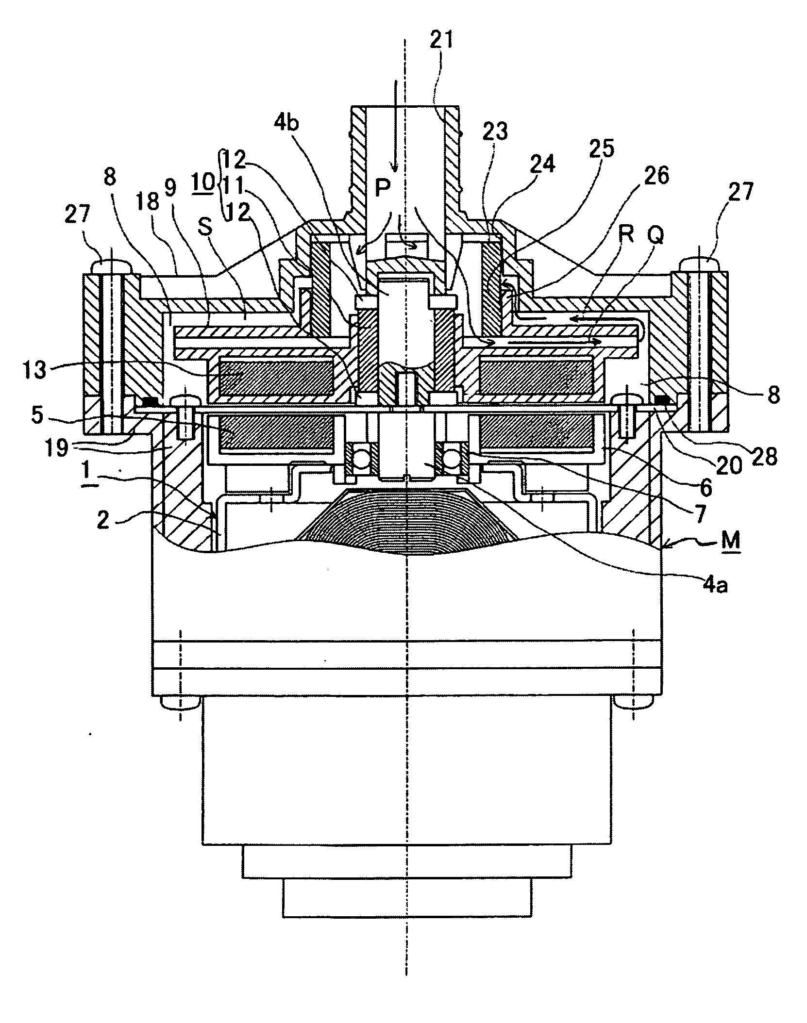
[0024]Preferred embodiments of the present invention will now be described in detail with reference to the attached drawings. First, the overall construction of a pump driving apparatus will be described with reference to FIG. 1 to FIG. 3.

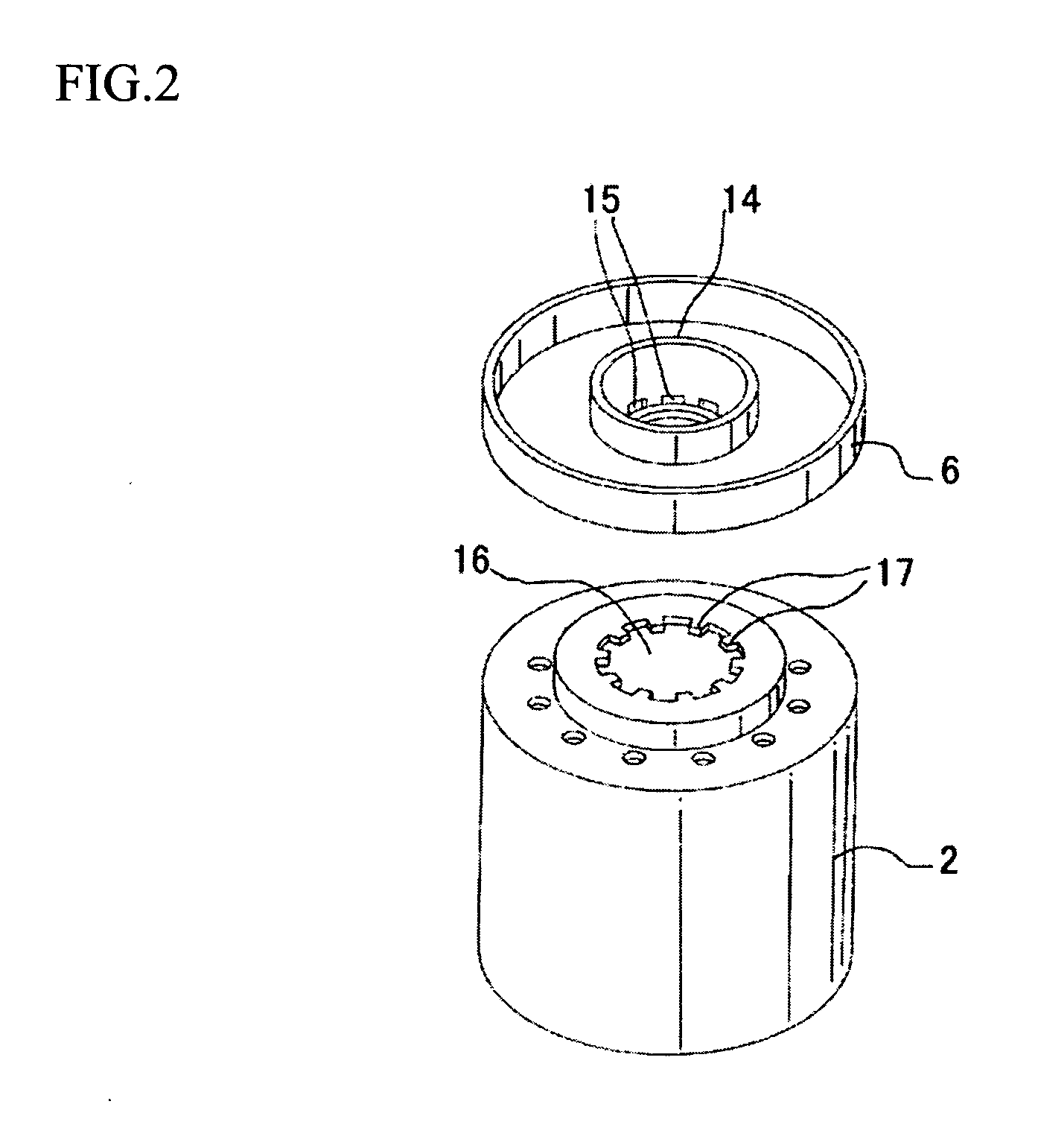
[0025]In FIG. 1, an example is shown where an outer-rotor, single-phase, bipolar brushless motor M is used as one example of a drive source for driving a pump. In this single-phase, bipolar brushless motor M, a rotor magnet (not shown) that is magnetized with two poles at 180° intervals is provided on a back yoke 2 of a rotor 1. The back yoke 2 is connected to a magnet case 6. A coupling magnet 5 is fitted into an upper surface of the magnet case 6. The magnet case 6 is rotatably fitted via a bearing 7 onto a motor-side fixed shaft 4a. Note that the rotor 1 is energized in the axial direction toward the magnet case 6 by a precompressed spring provided at a fixed end of the stator.

[0026]Here, the single-phase, bipolar brushless motor M is driven as ...


PUM


Abstract

A pump driving apparatus that can suppress backflow of a liquid in a pump chamber and improve pump efficiency is provided.
A guide tube 23 is provided coaxially with an output shaft 4 of a motor M inside a pump chamber 8, and the ends in the axial direction of the guide tube 23 are fitted into and make sliding contact with a case inner wall surface that forms the pump chamber 8 and a shaft core-side inner wall surface 25 of an impeller 9 enclosed inside the pump chamber 8.

Description

TECHNICAL FIELD[0001]The present invention relates to a pump driving apparatus that draws liquid in an axial direction into a pump chamber and expels the liquid in a circumferential direction by rotating an impeller provided inside the pump chamber.BACKGROUND ART[0002]First, one example of a pump driving apparatus will now be described. In FIG. 6, a rotor magnet 53, which has been magnetized with two poles at 180° intervals, is provided on a back yoke 52 of a rotor 51. The back yoke 52 is connected to a magnet case 56. A coupling magnet 55 is fitted onto the upper surface of the magnet case 56. The magnet case 56 is rotatably fitted onto a motor-side fixed shaft 54a via a bearing 57. A pump-side fixed shaft 54b, which is connected to a motor-side fixed shaft 54a by screw engagement, is integrally provided on a pump chamber 58. A rotation vane (impeller) 59 is fitted onto the pump-side fixed shaft 54b via a bearing 60. The impeller 59 slidably rotates via the bearing 60 around the pu...

Claims


Application Information

Patent Timeline
IPC IPC(8): F04D29/44
CPCF04D29/167F04D13/0666
Inventor KOMATSU, FUMITO
Owner YG K R & D
Why Eureka
Try Eureka