Plasma display panel cutting method, plasma display panel recycling method and plasma display panel cutting apparatus
a plasma display panel and cutting method technology, applied in the direction of electrode system manufacturing, glass recycling, electric discharge tube/lamp manufacturing, etc., can solve the problems of washing and sludge treatment, and achieve the effect of reducing facility costs and efficient cutting
- Summary
- Abstract
- Description
- Claims
- Application Information
AI Technical Summary
Benefits of technology
Problems solved by technology
Method used
Image

Examples
first preferred embodiment
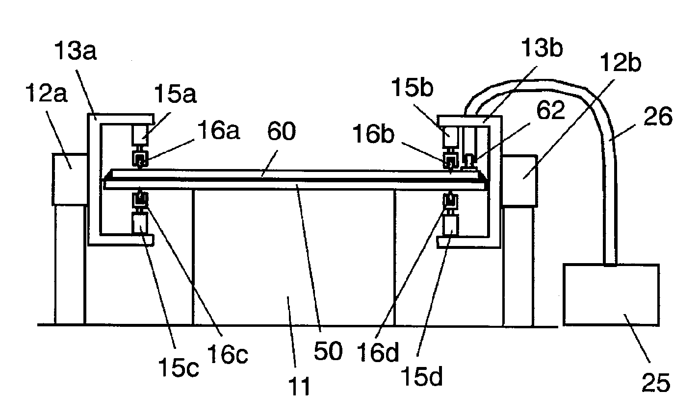
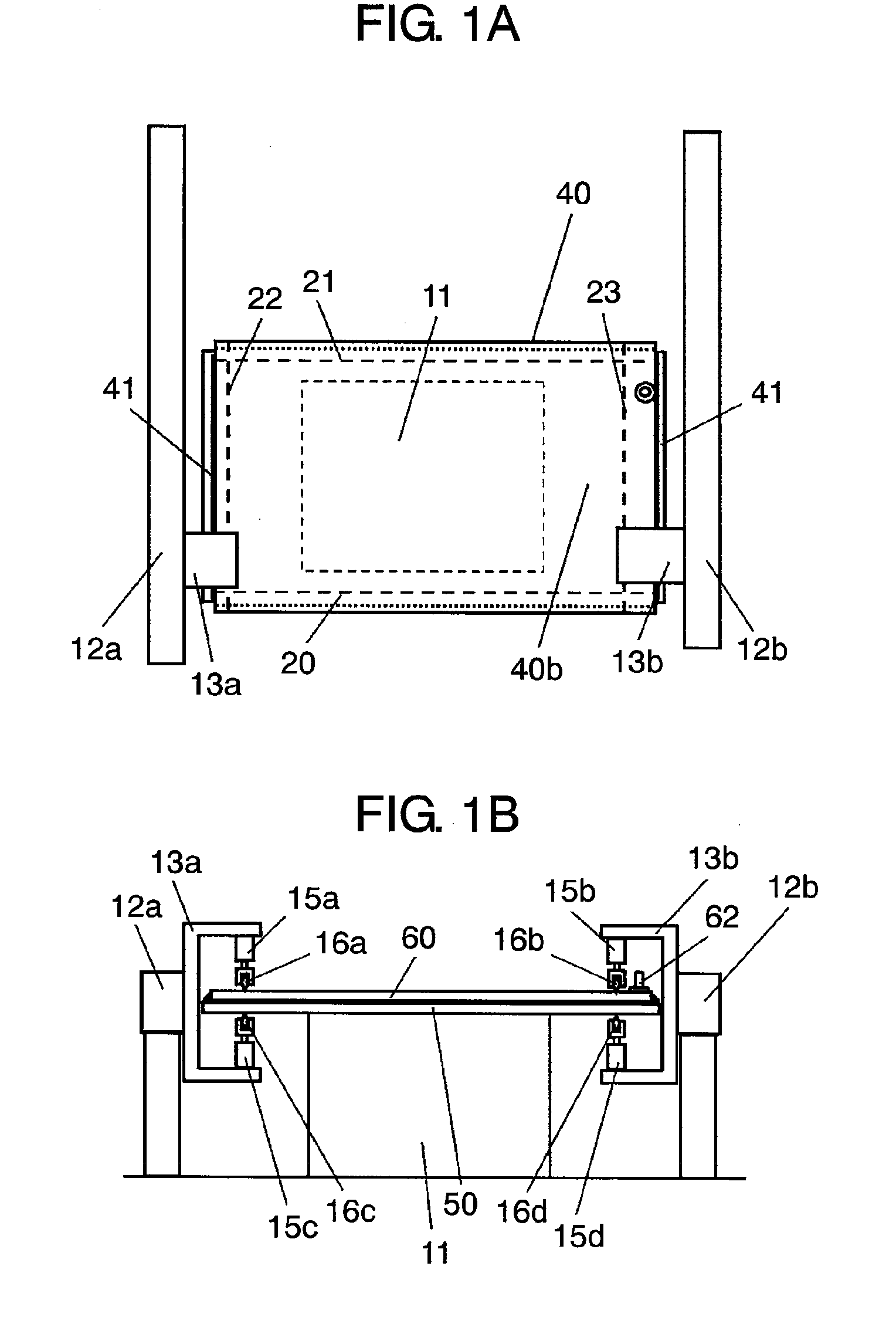
[0074]FIG. 1A is a plan view illustrating a PDP cutting apparatus according to a first preferred embodiment of the present invention. FIG. 1B is a front view illustrating the PDP cutting apparatus according to the first preferred embodiment.
[0075]In FIGS. 1A and 1B, the PDP cutting apparatus is constituted as follows.
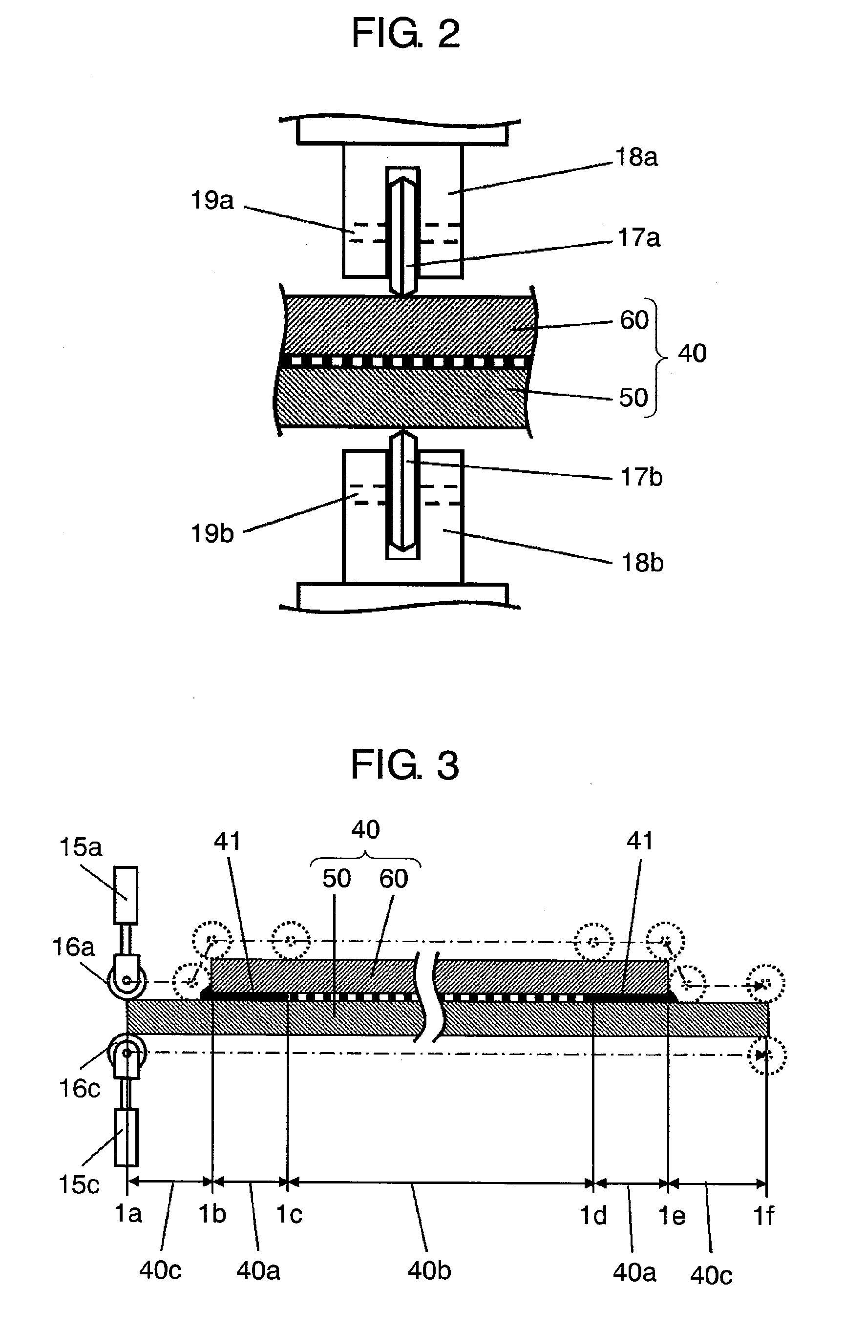
[0076]The PDP cutting apparatus includes glass cutting members 16a, 16b, 16c and 16d provided so as to sandwich front glass substrate 50 and rear glass substrate 60 of PDP 40, glass cutting member pressing devices 16a, 15b, 15c and 15d for pressing glass cutting members 16a, 16b, 16c and 16d to front glass substrate 50 and rear glass substrate 60 so that they contact the substrates, and glass cutting member running devices 12a and 12b for running glass cutting members 16a, 16b, 16c and 16d along front glass substrate 50 and rear glass substrate 60.
[0077]Front glass substrate 50 is fixedly adsorbed by a vacuum hole (not shown) provided on an upper surface of table 11 whi...
second preferred embodiment
[0114]A second preferred embodiment of the present invention is different to the first preferred embodiment as follows. In the first preferred embodiment shown in FIG. 1A, rotating cutters 16a, 16b, 16c and 16d are fun from the one ends of front glass substrate 50 and rear glass substrate 60 to the other ends thereof by sliders 12a and 12b so that the peripheral parts of front glass substrate 50 and rear glass substrate 60 are cut off.
[0115]In the second preferred embodiment, the traveling positions of rotating cutters 16a, 16b, 16c and 16d by sliders 12a and 12b in the latitudinal direction of the glass substrates stay in the range of lines 20 to 21 and do not fall on the both ends of the glass substrates. Next, table 11 is rotated through 90 degrees, the traveling positions of rotating cutters 16a, 16b, 16c and 16d by sliders 12a and 12b in the longitudinal direction of the glass substrates stay in the range of lines 22 to 23. Accordingly, glass-substrate central parts 40b of fron...
third preferred embodiment
[0121]In the first and second preferred embodiments, rotating cutters 16a, 16b, 16c and 16d are pressed onto front glass substrate 50 and rear glass substrate 60 when they are run thereon, and the cracks reaching the rear surfaces of the substrates are thereby formed so that the substrates are cut.
[0122]In a third preferred embodiment of the present invention, a method, in which the cracks do not reach the rear surfaces, and a pressure of fluid injected from an exhaust pipe is used to cut the scribed section, is described.
[0123]FIG. 5A is a plan view illustrating a PDP cutting apparatus according to the third preferred embodiment. FIG. 5B is a front view illustrating the PDP cutting apparatus according to the third preferred embodiment.
[0124]The cutting apparatus shown in FIGS. 5A and 5B is different to the apparatus shown in FIGS. 1A and 1B in that tube 26 serving as a fluid injecting pipe and connected to air-pressure pump 25 serving as a fluid injecting device is connected to exh...
PUM
| Property | Measurement | Unit |
|---|---|---|
| thickness | aaaaa | aaaaa |
| pressure | aaaaa | aaaaa |
| thickness | aaaaa | aaaaa |
Abstract
Description
Claims
Application Information
 - R&D
- Intellectual Property
- Life Sciences
- Materials
- Tech Scout
- Unparalleled Data Quality
- Higher Quality Content
- 60% Fewer Hallucinations
Browse by: Latest US Patents, China's latest patents, Technical Efficacy Thesaurus, Application Domain, Technology Topic, Popular Technical Reports.
© 2025 PatSnap. All rights reserved.Legal|Privacy policy|Modern Slavery Act Transparency Statement|Sitemap|About US| Contact US: help@patsnap.com