Robot-cell calibration

a robot and cell technology, applied in the field of robot cell calibration, can solve the problems of only a portion of the problem of robot calibration, the single “nominal” kinematic model cannot accurately represent the position of each individual robot, and the problem of transporting bulky measurement equipment, etc., and achieves the effect of convenient transportation and cost-effectiveness

Inactive Publication Date: 2009-06-18
DYNALOG
View PDF10 Cites 106 Cited by
  • Summary
  • Abstract
  • Description
  • Claims
  • Application Information

AI Technical Summary

Benefits of technology

[0019]The present invention proposes a robot cell calibration solution based on a practical small-range measurement device, addressing actual implementation issues faced in any industrial environment. The solution proposed herein is therefore not only cost-effective and easy to transport,

Problems solved by technology

As a result, a single “nominal” kinematic model will not accurately represent the position of each individual robot.
However, calibration of the robot only resolves a portion of the problem.
This in turn raises the issue of transporting bulky measurement equipment.
Furthermore, such large-scale high-accuracy measurement systems are intrinsically too expensive to acquire for most robot end-users.
Finally, most of these high-end measurement devices require delicate operation, often involving a lengthy setup time (if only for heating temperature to stabilize) and necessitating highly qualified operators.
However, one of the negatives of the DynaCal system is the potential interference between its measurement cable and its surroundings, therefore sometimes complicating the location of the DynaCal unit within a typical fixture.
The use of a small-range measurement device instead, obviously limits the motion of the robot within a small volume.
This particular method not only suffers from the drawback mentioned above (i.e. limited parameter exercise resulting in poor accuracy), but additionally it is very time-consuming and highly prone to manual teaching errors, all that therefore dramatically reducing the practical use and effectiveness of this method.
However, this method, although automatic, is slow since the robot is required to move at low speed in order to make contact at a position in space that can be reliably recorded.
More im

Method used


Image

  • Robot-cell calibration
  • Robot-cell calibration
  • Robot-cell calibration

Examples


Embodiment Construction

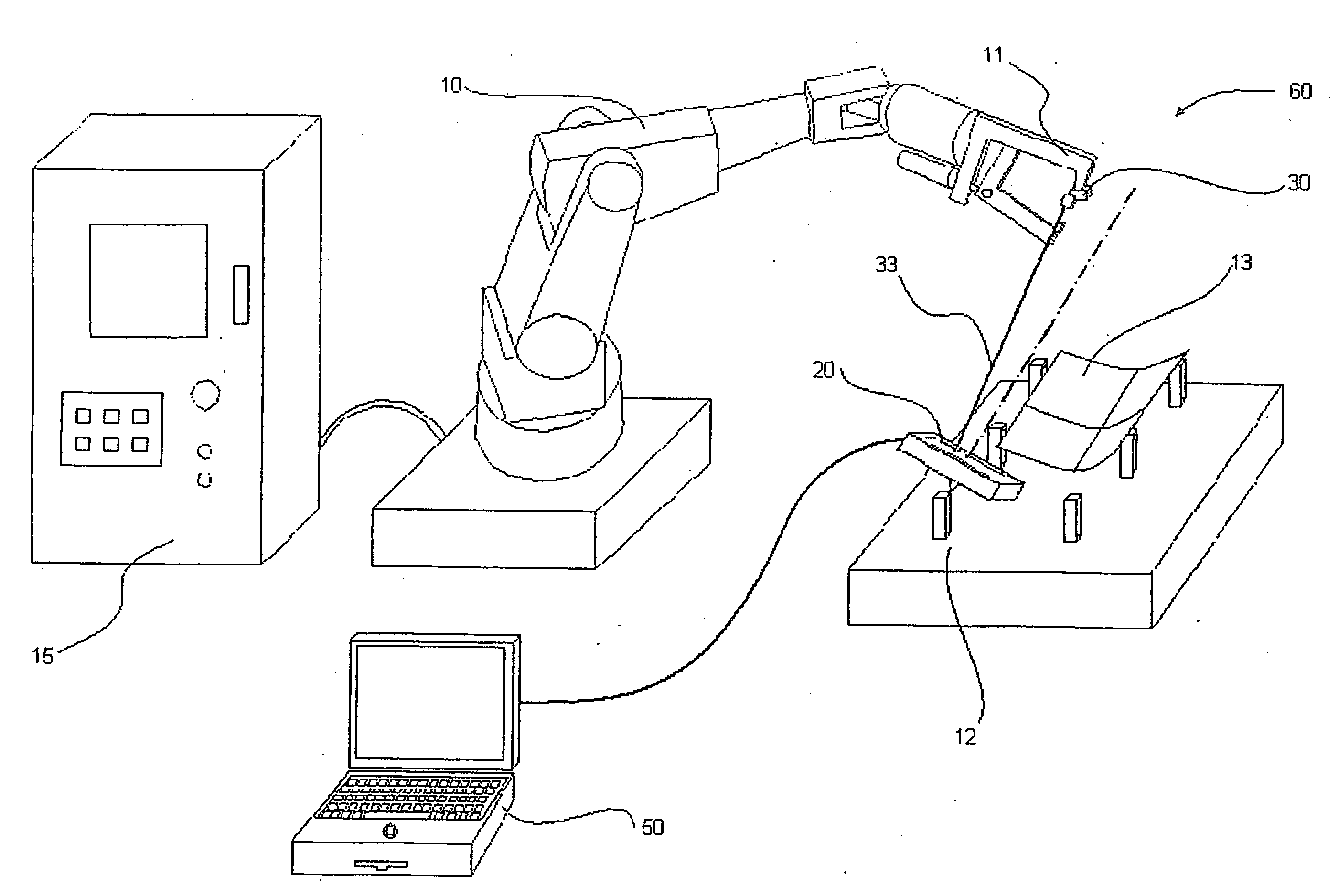
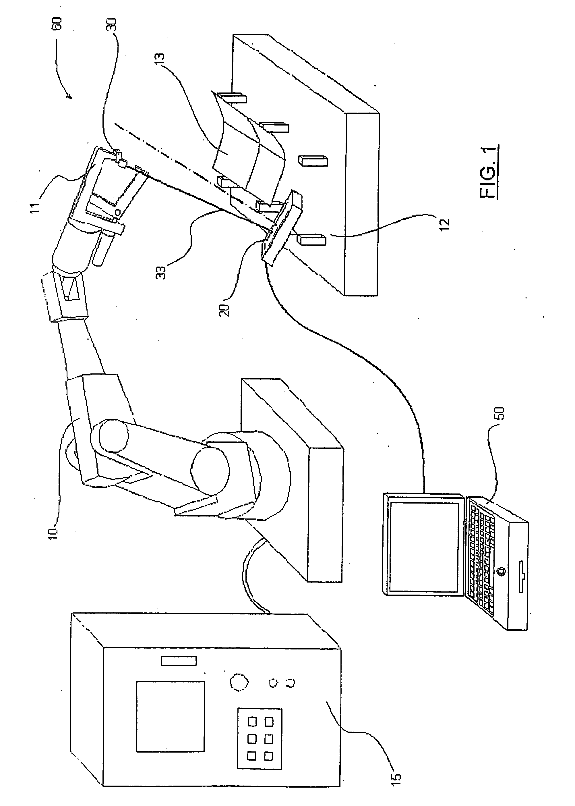
[0036]The method and apparatus of the present invention will be described in conjunction with the drawings. It will be understood, however, that the method of the present invention will have applications in other areas of manufacturing and that the description of the present invention with respect to the described embodiments is by way of example only.

[0037]The calibration system 60 of the present invention is shown generally in FIG. 1 as used to perform calibration of an industrial robot 10 connected to a robot controller 15. The robot 10 would typically include an end-effector 11 which might be a tool or some other device rigidly connected to and manipulated by the robot 10. Typically, a fixture 12 holding a part 13 sits in front of the robot 10 that is performing a specific task on the part 13 (e.g. arc welding or laser cutting).

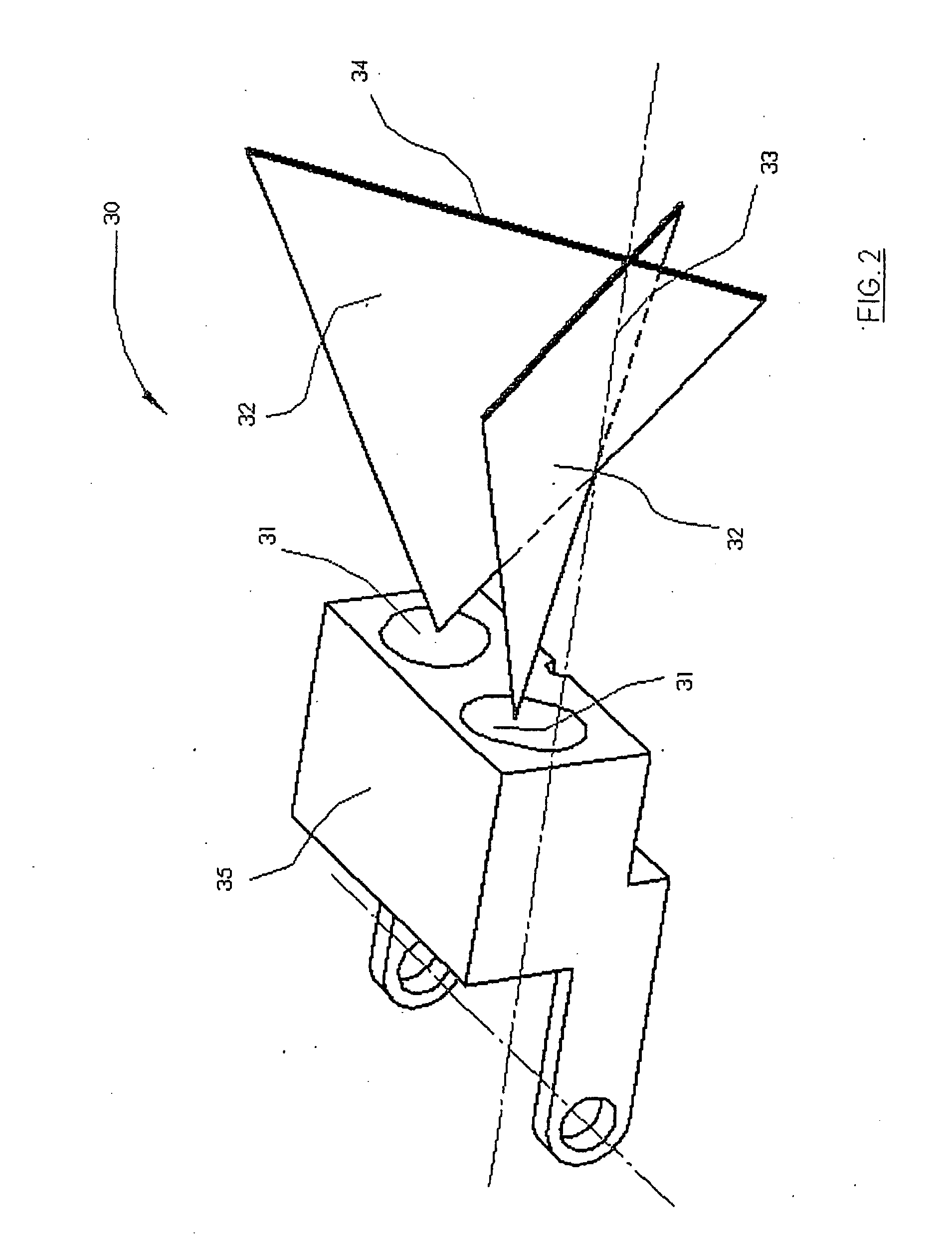
[0038]The calibration system 60 consists primarily of two components: an emitter 30 and a receiver 20. The emitter 30 (see FIG. 2 and FIG. 3) generally c...


PUM


Abstract

A calibration system for a robot and its peripheral includes an emitter attached to the robot or its peripheral and emits a laser beam and a receiver also mounted to the robot or its peripheral at a point to permit calibration and for receiving the laser beam and to permit calculations to determine the dimension between the emitter and the receiver.

Description

RELATED APPLICATION[0001]This application claims priority of U.S. Provisional Patent Application Ser. No. 60 / 629,359 filed Nov. 19, 2004, which is incorporated herein by reference.BACKGROUND OF THE INVENTION[0002]The present invention relates to calibration of a standard industrial robot, as well as of most its peripherals (i.e. end-effector, fixture, etc.). More specifically, it is based on the use of a small-range measurement device, paired with a virtual extension (typically mounted on the robot). Compared to the current technology, the present solution is very portable, cost-effective and highly practical, while at the same time inherently maximizing the accuracy of the calibration process.DESCRIPTION OF THE PRIOR ART[0003]There are a variety of solutions currently used to perform calibration of a typical industrial robot, and optionally of some of its peripherals as well (e.g. end-effector or fixture). The vast majority of these solutions are based on the use of a large-range e...

Claims


Application Information

Patent Timeline
IPC IPC(8): G12B13/00G06F19/00B25J9/16G01B11/14
CPCB25J9/1692G01B11/002Y10S901/50Y10S901/02G05B2219/37275
Inventor DE SMET, PIERRE
Owner DYNALOG
Why Eureka
Try Eureka