Emission Treatment System

a technology of emission treatment and filter, applied in the direction of separation processes, machines/engines, mechanical equipment, etc., can solve the problems of sub>2 /sub>ratio entering the filter, and achieve the effect of improving the control of the downstream selective catalytic reduction catalys

Active Publication Date: 2009-06-25
BASF CORP
View PDF49 Cites 39 Cited by
  • Summary
  • Abstract
  • Description
  • Claims
  • Application Information

AI Technical Summary

Benefits of technology

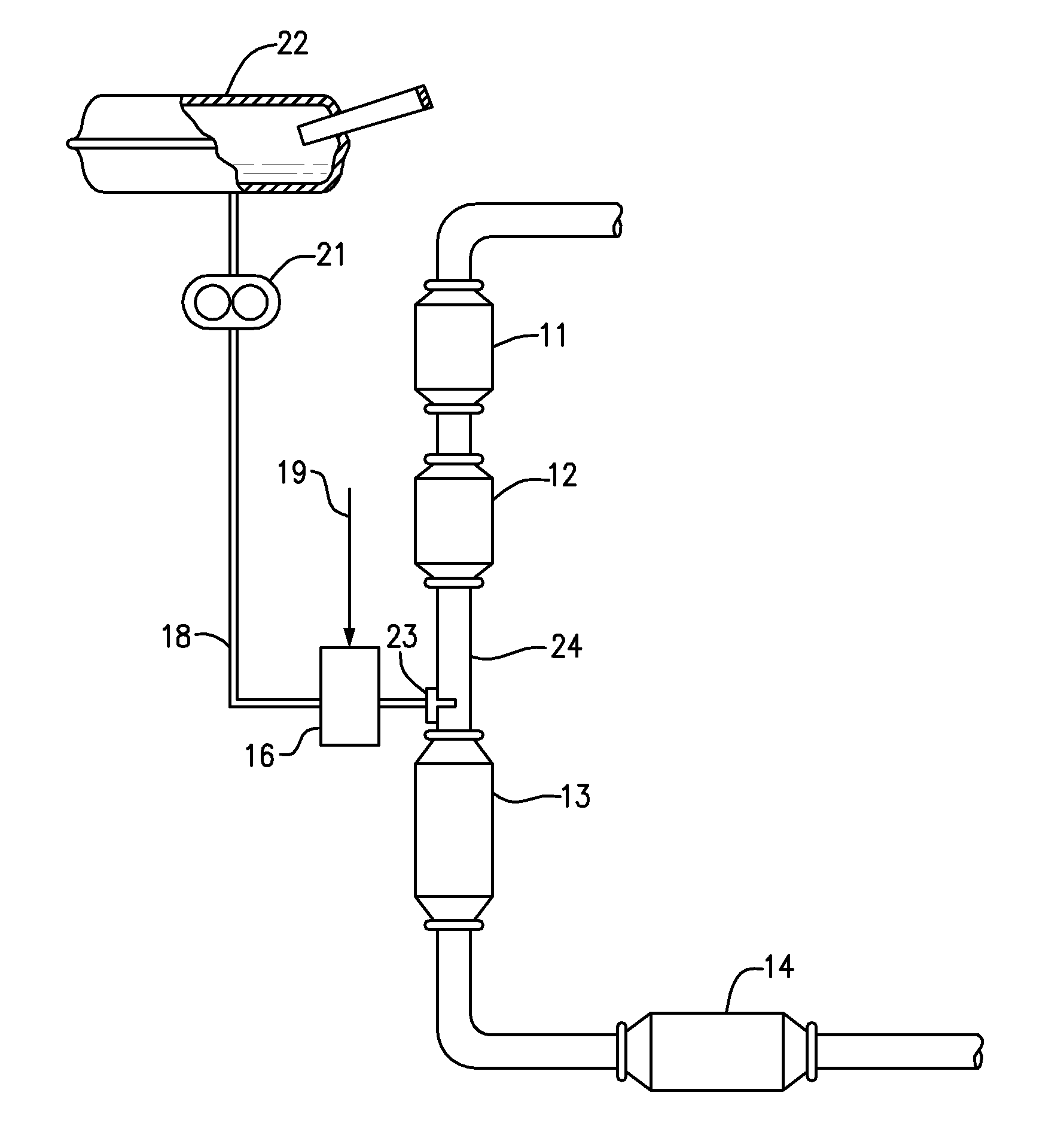
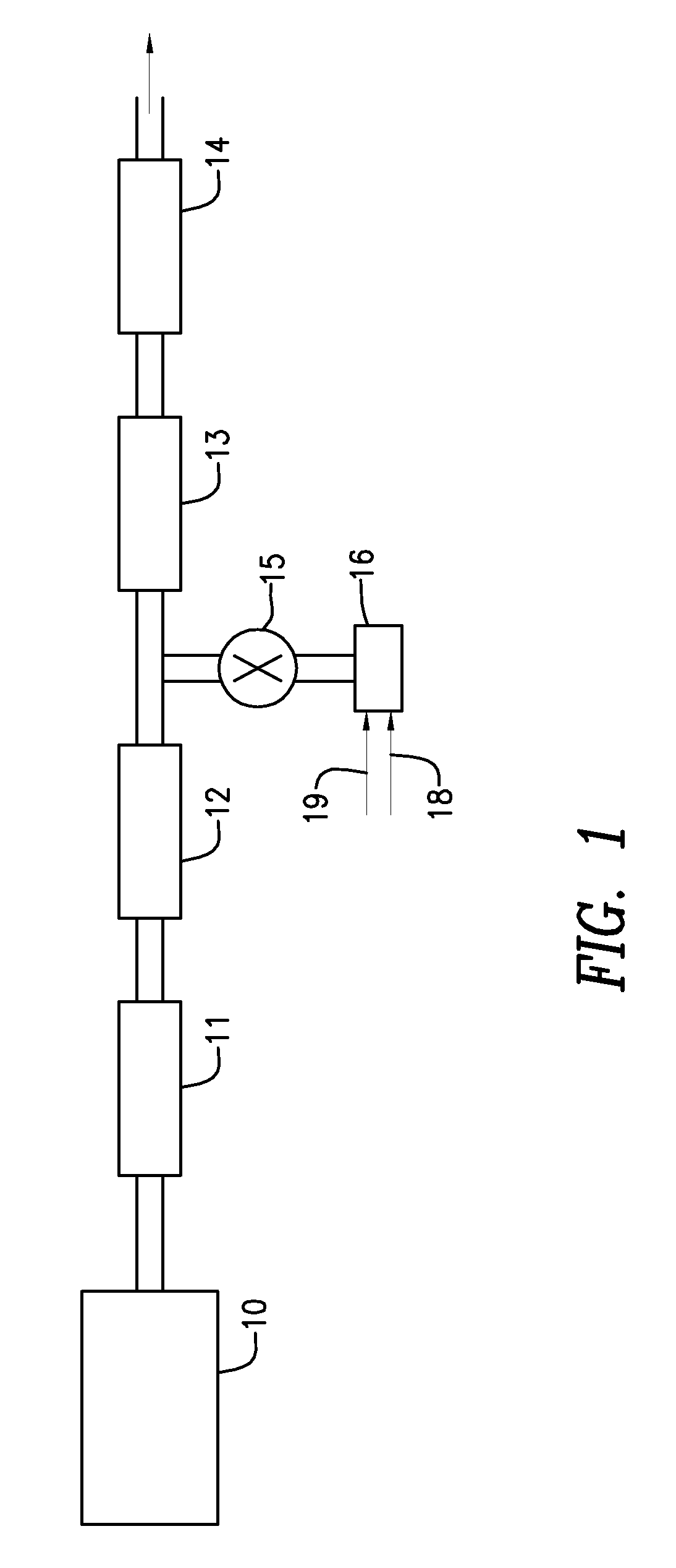
[0020]Additional embodiments are to methods of treating an exhaust gas stream from a diesel engine, where the exhaust gas stream comprising NOx and particulate matter. These methods comprise suppressing the NO2 production

Problems solved by technology

Applicants have determined that in systems such as the type in which a DOC is located upstream from a CSF, which is located upstream from an SCR catalyst, the optimal

Method used


Image

  • Emission Treatment System
  • Emission Treatment System
  • Emission Treatment System

Examples


Embodiment Construction

[0034]Before describing several exemplary embodiments of the invention, it is to be understood that the invention is not limited to the details of construction or process steps set forth in the following description. The invention is capable of other embodiments and of being practiced or being carried out in various ways.

[0035]“Activated alumina” has its usual meaning of a high BET surface area alumina, comprising one or more of gamma-, theta- and delta aluminas.

[0036]“BET surface area” has its usual meaning of referring to the Brunauer, Emmett, Teller method for determining surface area by N2 absorption. Unless otherwise specifically stated, all references herein to the surface area of the catalyst support components or other catalyst components means the BET surface area.

[0037]“Bulk form,” when used to describe the physical form of a material (e.g., ceria), means the material is present as discrete particles that can be as small as 1 to 15 microns in diameter or smaller, as oppose...


PUM

PropertyMeasurementUnit
Fractionaaaaaaaaaa
Ratioaaaaaaaaaa

Abstract

An emission treatment system and method for remediating the nitrogen oxides (NOx), particulate matter, and gaseous hydrocarbons present in diesel engine exhaust streams are described. The emission treatment system has an oxidation catalyst upstream of a soot filter upstream from a NOx reducing catalyst.

Description

[0001]This application claims the benefit of priority under 35 U.S.C. § 119(e) to U.S. Patent Application No. 61 / 012,947, filed Dec. 12, 2007, which is hereby incorporated by reference in its entirety.BACKGROUND[0002]The present invention relates to an emission treatment system having a Diesel Oxidation Catalyst (DOC) positioned upstream from a Catalyzed Soot Filter (CSF), which is positioned upstream from a Selective Catalytic Reduction (SCR) catalyst. In one or more embodiments, the system provides an effective method of simultaneously remediating the nitrogen oxides (NOx), particulate matter, CO and gaseous hydrocarbons present in diesel engine exhaust streams.[0003]Diesel engine exhaust is a heterogeneous mixture which contains not only gaseous emissions such as carbon monoxide (“CO”), unburned hydrocarbons (“HC”) and nitrogen oxides (“NOx”), but also condensed phase materials (liquids and solids) which constitute the so-called particulates or particulate matter. Often, catalyst...

Claims


Application Information

Patent Timeline
IPC IPC(8): F01N3/035F01N3/20
CPCB01D53/9418Y02T10/24B01D53/944B01D53/945B01D53/9477B01D53/9495B01D2251/2067B01D2255/102B01D2258/012F01N3/0231F01N3/0821F01N3/2066F01N2570/18F01N2610/02Y02C20/10Y02T10/22B01D53/9436Y02T10/12
Inventor HALLSTROM, KEVIN A.KUMAR, SANATH V.STIEBELS, SUSANNEVAARKAMP, MARIUS
Owner BASF CORP
Why Eureka
Try Eureka